| Author |
 Topic Topic  |
|
jcsifu
Copper Member
USA
47 Posts |
 Posted - 11/07/2009 : 16:56:03 Posted - 11/07/2009 : 16:56:03


|
I want to substitute a BS170 MOSFET at Q2 in a DS-1 and I'm not sure which pins would go where. Is it that D = C, G = B, and S = E? I have been trying to search for the answer, but I am not familiar with MOSFETS and all the datasheets just list pin outs and not functions. Any help is greatly appreciated.
|
|
|
Laurie
Double Platinum Member

Canada
4854 Posts |
Posted - 11/07/2009 : 17:03:53

|
| G'day! Not sure a swap from a BJT to MOSFET is doable without a major revision to the circuit... Is this from a standard mod somewhere? |
 |
|
|
jcsifu
Copper Member
USA
47 Posts |
Posted - 11/07/2009 : 17:40:22
|
Hi Laurie, this is CCTSIM's mod he posted on another forum:
One mode (of mine, I call it SHO173) I really liked recently was to replace the CE stage around Q2 with a MOSFET. It goes like this:
Replace R6 with a 1M resistor
Replace R7 with a 1M resistor
Replace R8 with a 5.6k resistor
Replace Q2 with BS170 MOSFET (careful here, C-B-E doesn't map 1-to-1 to D-G-S)
Replace R9 with a a 4.7k or 5k trim potentiometer
Remove C4
Replace C3 with a 0.1uF metal film capacitor
Replace C5 with a 1uF metal film capacitor ( initially I used 10uF but sounded too buzzy)
Adjust the gain of the booster with the trim pot. to your liking and have fun.
I ended up replacing the trim pot. with the on/off/on toggle switch I had from another mod to have 3 gain presets
accessible from the outside.
As you probably have guessed it, the CE stage is replaced with a ZVEX SHO that costs ~ �173 here (that I don't have).
Essentially, a �173 upgrade to a DS-1.
I thought it looked like a good place to take a DS-1, but like I said I don't know the match up. |
|
|
|
cctsim
Silver Member

United Kingdom
418 Posts |
Posted - 11/07/2009 : 18:10:34
|
This is a mod I did for me and a few friends. It replaces the the CE stage of the DS-1 with a ZVEX SHO MOSFET booster. I posted the mod originally on freestompboxes.org.
The mapping of the electrodes is as follows:
C -> D
B -> G
E -> S
(so you've guessed correctly)
However, check the datasheet from the manufacturer of your BS170 device for the order of the electrodes. Some bending might be required.
|
Edited by - cctsim on 11/07/2009 18:11:57 |
|
|
|
Laurie
Double Platinum Member
Canada
4854 Posts |
Posted - 11/07/2009 : 18:41:51
|
| Ahhh... gotcha! Looks like a winner. Let us know how it sounds? |
|
|
|
jcsifu
Copper Member
USA
47 Posts |
Posted - 11/07/2009 : 23:42:55
|
Thank you CCTSIM, I will check and use shrink tube to do the bends. Very much looking forward to something different. Maybe it's just my ears getting older, but at stage volume at least, it is getting difficult for me to hear any big differences in od and dirt boxes at similar settings.
L- I'll do this mod over the weekend and post the results. |
|
|
|
jcsifu
Copper Member
USA
47 Posts |
Posted - 11/08/2009 : 08:48:19
|
Finished the mod and got to play a little before going out tonight.
I'm wondering if I got this right.
This is now a very low output pedal with little to no distortion. I'm not sure what I would call this, not and od because the low output, not a dirt box cause it has only a little bite to it. It adds a bit of attack and a different voice to things and makes things a little fuller, but it needs to be wide open on drive and volume to do so. I like it and I am looking forward to trying it live as I suspect it will cut through everything well for solos. I would like to get more volume from it though, and maybe a little more distortion too.
CCTSIM, does this sound right? Is there a way to raise the output level in order to hit my amp harder? Maybe adding another diode in series with the clippers? I played around with the trim pot and then tried the R13 C8 gain change and did find more available bite but there is probably a better way to increase volume.
Much thanks in advance. |
Edited by - jcsifu on 11/08/2009 08:52:08 |
|
|
|
cctsim
Silver Member
United Kingdom
418 Posts |
Posted - 11/08/2009 : 09:56:21
|
Something doesn't sound right in your implementation. It should have tons of volume and distortion available, like a tube ready to explode.
The MOSFET booster typically should have more output level than the original CE stage, unless you have set up the trim potentiometer at R9 very high, which will give unity gain.
The other possible problem could be that the BS170 was installed wrong.
Do you get different gains when you turn on the trim pot ? small values for R9 will give you higher gain. The highest gain is available when you replace R9 with a short.
Also you should hear a "crackle" when you turn the trim potentiometer. Is this audible ? This will indicate that the booster is working properly.
|
|
|
|
Laurie
Double Platinum Member
Canada
4854 Posts |
Posted - 11/08/2009 : 10:02:41
|
Hey cctsim... would a 2N7000 work here? Looks like an equivalent to the BS170 with the quick scan I gave it?
|
|
|
|
cctsim
Silver Member
United Kingdom
418 Posts |
Posted - 11/08/2009 : 10:21:42
|
| Yes, 2N7000 should work fine. They are a bit more noisy (hissy), at least the batch I have. |
|
|
|
jcsifu
Copper Member
USA
47 Posts |
Posted - 11/08/2009 : 21:27:29
|
| After 3 more tries all with new BS170's and 2 attempts with new 2N7000's, replacing the trim pot with a 1k resistor, then a 2.2, re-doing all the other component changes just to make sure I didn't miss anything, I have the same result.....no sound. The only time I was able to get sound out of the mod was when I first had the BS170 in, producing the results listing earlier. I have now placed the pedal in a spot far away from me and I won't even make eye contact with it...I'm so frustrated with this! There are only so many things that could be wrong, right? |
|
|
|
cctsim
Silver Member
United Kingdom
418 Posts |
Posted - 11/09/2009 : 01:59:10
|
Could you post any internal photos so that we can help further ?
This mod is very straightforward and shouldn't cause big issues. Also 1k at R9 will not give you a lot of gain. For the highest gain possible use a short for R9. Something between 47-220 will produce higher gain with acceptable noise levels.
|
|
|
|
jcsifu
Copper Member
USA
47 Posts |
Posted - 11/10/2009 : 03:47:19
|
The whole house is sick so I have been busy with the kids, I'll shoot some pics in the next day or two. Thanx again for taking the time to help me fix this, I really cannot imagine what is wrong unless it was one of my junk DS-1's (yes, I have a serious bad habit of buying too many cheap pedals when given the chance). Anyway, I don't think this is the case, but I'll put some gut shots up when things settle down here.
jc |
|
|
|
bside2234
Copper Member
USA
15 Posts |
Posted - 11/10/2009 : 17:44:56
|
| If I remember correctly, BS170's made by different companies have different pinouts. Make sure you are looking at the datasheet of the company that made the BS170's you are using. |
|
|
|
jcsifu
Copper Member
USA
47 Posts |
|
|
cctsim
Silver Member
United Kingdom
418 Posts |
Posted - 11/13/2009 : 00:54:32
|
The picture is not very clear but I think the swapping of the electrodes is wrong.
Here is a diagram for the pin layout:

Looking at the photo, the orientation of the transistor is ok, but you need to swap G and D (not G and S as you did). |
|
|
|
Topic |
|
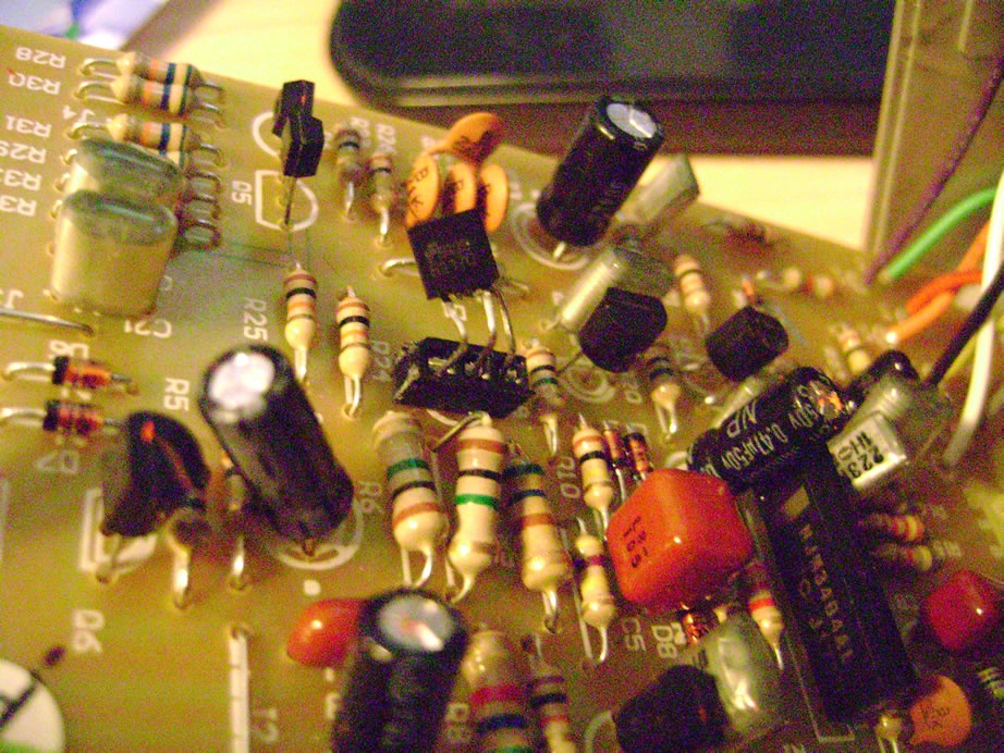 gutshot1.jpg
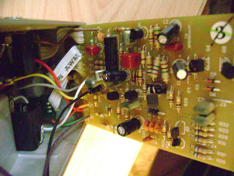 gutshot2.jpg