| Author |
 Topic Topic  |
|
|
ashtone
Copper Member
15 Posts |
 Posted - 09/15/2009 : 02:29:14 Posted - 09/15/2009 : 02:29:14


|
Hello all: I have an old post in here about my home-brewed true bypass mod. I originally used a pin switch elsewhere on the pedal case to replace the function of the momentary switch under the pedal lid. It had been brought to my attention that you can hard-wire the circuit to have the effect be on all the time, which eliminates the need for the pin switch. Obviously this will require modifying the circuit board, but I feel it is a more esthetically pleasing way to perform this mod than drilling the case for an additional switch. I would like to know how I can locate / identify the components on the circuit board that are used to switch the effect on/off when you step on the pedal. I am not referring to a specific Boss pedal as I am hoping the design is one Boss uses in all the compact pedals. I have attached a photo of my DC-2, with the pin switch on the left and a red/green LED on the right (for in/out status). Thanks in advance!
Download Attachment:  DC-2.zip DC-2.zip
667.68�KB |
Edited by - ashtone on 09/15/2009 02:40:20 |
|
|
cctsim
Silver Member

United Kingdom
418 Posts |
Posted - 09/15/2009 : 05:07:19
|
This is not a normal Boss switching circuit btw. The components involved are:
Resistors: R93, R94, R96
Capacitors: C54, C63
Chip: IC13
Diodes: D2, D9, D10
FETs: Q1, Q11, Q12
D11 and R95 are connected to LED.
Just a word of caution: there are buffering and emphasis/de-emphasis stages involved in this pedal that are in the mix with the switching circuit. They may cause problems unless you know what you are doing.
I'd leave the DC-2 intact and use an easier solution such as a looper pedal like this one by Keeley:

|
 |
|
|
ashtone
Copper Member
15 Posts |
Posted - 09/16/2009 : 01:03:04
|
Thanks for the reply. Buffering, emphasis, de-emphasis...is this true for all Boss pedals, or just the digital ones? If it is going to take advanced expertise to achieve (which I do not posess), I should stick with the pin switch, however unsightly it may be. I was under the impression that by deleting a few components or adding a jumper or two, I could hardwire the circuit so it is engaged at all times. Not so? And when you say "this is not a normal Boss switching circuit", do you mean that the DC-2 is unique in this respect?
Thanks,
John
here's a shot of the switch in the DC2 I altered, and the DD5 as well
Download Attachment: DC2 loop switch and shims.jpg
389.22 KB
Download Attachment: DD5 pin switch and LED 3.jpg
370.92 KB |
|
|
|
cctsim
Silver Member
United Kingdom
418 Posts |
Posted - 09/16/2009 : 11:10:32
|
Yes, DC-2 doesn't have the usual flip-flop circuit that you find in most boss pedals.
I may disappoint you, but what you have may not be true bypass as the buffers may still be included in the signal chain when the pedal is off. You didn't give us enough details of the internals to be able to tell exactly.
Here is the input and output circuits of DC-2:


If you look closer at the input, when the pedal is off, the signal will pass through R6 and up to C7.
The same applies at the output, the signal will pass through R71 up to R72.
The op-amp circuits and other electronic components will color your signal in bypass mode, even if the pedal is off.
If you want true bypass, your wiring should go from point 1 (in the schematic) at the input to point 9 and 10 at the output.
|
Edited by - cctsim on 09/16/2009 11:16:18 |
|
|
|
ashtone
Copper Member
15 Posts |
Posted - 09/16/2009 : 23:09:47
|
| Thanks for replying. I think I do have true bypass, as what I have done is to install a mechanical A/B loop switch (4PDT)in the space normally occupied by the factory effect on/off switch. The effect is always on, and the switch I put in sends the input signal to the circuit board and then to the output jack, or directly from the input jack to the output jack. It also switches a two-color LED from red (effect) to green (bypass). Stereo in/out is maintained when applicable. My issue is eliminating the little pin switch because of the esthetics. can you tell me how I would find the information I need to hardwire the circuit to be "on"? I have an old Tube Screamer and a number of other Boss analog pedals I want to put this in, hopefully without the pin switch. Pedal board real estate as well as finances become an issue when trying to have an A/B loop box for each and every pedal. |
|
|
|
cctsim
Silver Member
United Kingdom
418 Posts |
Posted - 09/16/2009 : 23:36:22
|
Conversion to "always on" is easy. You just need to remove one transistor from the switching flip flop.
If you tell us which pedal, I might be able to tell you the transistor number, provided there is a schematic available for that pedal.
|
|
|
|
ashtone
Copper Member
15 Posts |
Posted - 09/18/2009 : 18:07:40
|
Great news! So here you go:
DS-1, SD-1, CS-3, BF-2, CE-2, DD-3, DD-5, RV-3, PH-1R, PN-2,
and DC-3. If there is no schematic available, can I figure it out by the location or type of the transistor?
Thanks for your help.
John |
|
|
|
cctsim
Silver Member
United Kingdom
418 Posts |
Posted - 09/18/2009 : 23:34:30
|
The transistors involved in the switching flip-flops are:
BF-2: Q9 & Q10
CE-2: Q6 & Q7
CS-3: Q2 & Q3
DD-3: which version ?
DD-5: not possible
DS-1: Q4 & Q5
PH-1R: schematic not available
PN-2: schematic not available
RV-3: not possible
SD-1: Q4 & Q3
You need to remove the first transistor. |
|
|
|
archimedes
Silver Member
United Kingdom
191 Posts |
Posted - 09/18/2009 : 23:47:15

|
quote:
Originally posted by ashtone
Thanks for replying. I think I do have true bypass, as what I have done is to install a mechanical A/B loop switch (4PDT)in the space normally occupied by the factory effect on/off switch. The effect is always on, and the switch I put in sends the input signal to the circuit board and then to the output jack, or directly from the input jack to the output jack. It also switches a two-color LED from red (effect) to green (bypass). Stereo in/out is maintained when applicable.
That sounds really interesting, could you possibly provide some info on what switches you have used and how you have wired it?
Thanks
David |
|
|
|
bassinyourface
Bronze Member

France
76 Posts |
Posted - 09/19/2009 : 09:28:03
|
 Thanks cctsim ! Thanks cctsim !
Some very nice info ! |
|
|
|
ashtone
Copper Member
15 Posts |
Posted - 09/23/2009 : 06:52:39
|
CCTISM:
Thanks for your help. When you say remove the "first" transistor, you are referring to the order you listed them in, and not the order they are in the circuit, correct? And it just needs to be removed, no jumper or other wiring needed?
As for the DD-3, it is made in Japan, and has a number on the circuit board: 7527352000; TEAEC1 94HB. Hope that helps. Thanks again.
Ashtone |
|
|
|
ashtone
Copper Member
15 Posts |
Posted - 10/11/2009 : 19:33:39
|
David:
I don't know how much of my posting you have read, so I will be as complete as I can: it is a 4PDT switch, installed in place of the factory switch and wired as an A/B loop between the input/output jacks and the circuit board. 4PDT provides input, output A, output B (if applicable) and a two-color LED for loop status.
The installation is relatively simple, but the switch position vertically is pretty specific and requires some trial and error to get right, as the travel of the case lid to latch/unlatch the switch is limited by the travel of the access screw. This means adding/removing spacers until you get it right. Additionally, the removal of the factory switch requires either hard-wiring the circuit to be permanently "on", which is an option on analog pedals, but not on digital pedals. (This is according to all the information I have been able to obtain from people who know alot more than I do about electronic design). I eliminate this circuit modification by adding a tiny pin switch to replace the factory momentary switch. Consequently, I have to drill two holes to add the pin switch and the LED. (See my earlier posts for photos) This doesn't bother me, but I realize some folks don't like to drill the case since it is irreversible. So, if you get the info you need to locate the transistors, you could hardwire an analog pedal, but I have been advised not to try to hardwire a digital pedal. I also think that since my mod allows you to use a battery if you choose, the pin switch lets you shut the factory LED off to extend battery life. A small consideration, I admit, but not an unreasonable one. Being one who appreciates clean, finished-looking work, I thread the hole for the pin switch and screw it in from the inside, so there is no nut on the outside. This means I have to remove everything from the case before drilling and threading, which takes extra time. It takes me 3-4 hours to do each pedal. |
|
|
| |
Topic |
|
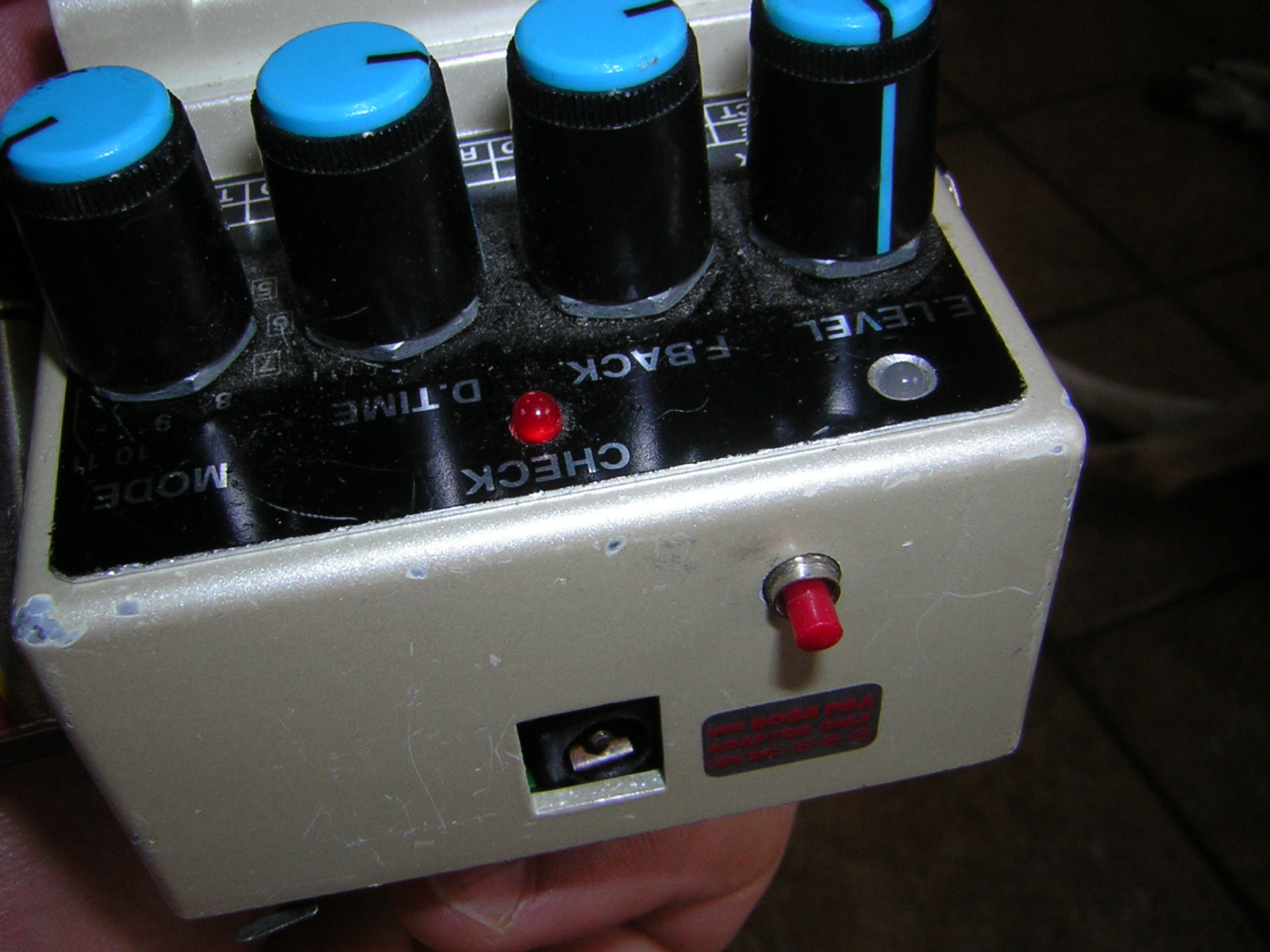 DD5 pin switch and LED 3.jpg