| Author |
 Topic Topic  |
|
Laurie
Double Platinum Member

Canada
4854 Posts |
 Posted - 01/18/2009 : 06:54:59 Posted - 01/18/2009 : 06:54:59


|
Lets summarise what we can deduce:
1) for the LED to be working, the flip-flop is functioning
2) basic power must be getting onto the board or no signal would be passing
Now, for symptoms we have:
a) the effected and bypass signal paths seem to tbe "tangled"
b) the effected signal path has a failure in the EQ
c) the effected signal path has a failure in drive
Thinking out loud, it sounds like there may be a failure in the FET switching...
Consider:
- Q9 always off = no drive to the effect circuit, so nothing from the drive or EQ controls
- Q2 and Q3 always on = the level pot would always be in parallel with the output - which could give the type of function described
BUT the LED switches on and off and the LED is in the gate circuit of Q3, so Q3 should be switching. It seems unlikely that Q2 and Q3 would both have failed at the same time.
So I think we are still looking for something more "global". Maybe it is just the opamps failed from reverse voltage or something.
Any chance you could make up a signal probe (like a recent post in the FAQ forum)? We could test the signal at various points through the pedal and see where its dying.
If you can do some probing, turn the pedal on (LED lit), send a signal to the input and see what you get at these points (doesn't matter which side of the component you put the probe):
- C39
- C33
- C29
- C3
- C4
- C11
|
 |
|
|
ScottC
Copper Member
USA
20 Posts |
Posted - 01/18/2009 : 16:07:24
|
Thanks CC and Laurie for your knowledge, it is much appreciated. This is a great learning experience for me and my son.
I'll build the probe and do what you suggested Laurie, but it may take a couple days. I've got a few other projects around the house that I need to get done first. Hopefully by Monday or Tuesday night, I'll report what I find.
Thanks again. |
|
|
|
ScottC
Copper Member
USA
20 Posts |
Posted - 01/19/2009 : 00:14:24
|
Well, I finished the other things on my to do list and got to this. Here's what I got:
C39 sound, but none of the knobs affect the sound at all
C33 same as above, sound, but knobs have no impact on it
C29 no sound with light strumming on guitar, pops and crackles with heavy strumming
C3 sound, volume knob adjust volume a little, but not much, other knobs have no impact on sound
C4 sound, but none of the knobs affect sound at all
C11 no sound at all.
Hope these clues help.
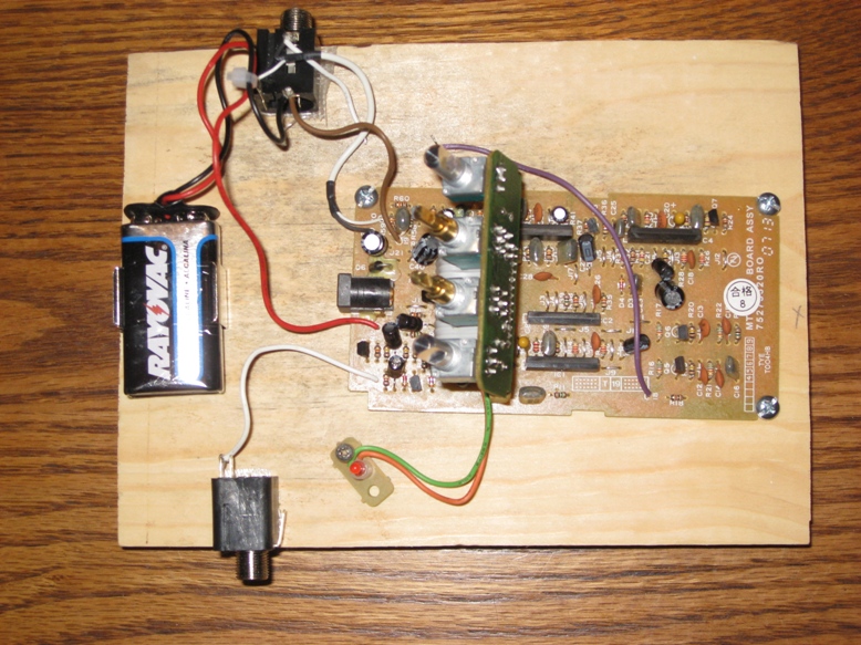
And, just if you're interested, I'm attaching photos of my high tech diagnostic tools. Not shown in the photo of the innards of the Metalzone is a ground wire I connected between the two jacks.
Thanks.
Download Attachment:  test board.JPG test board.JPG
259.46�KB
tongue depresser with capacitor taped to it
Download Attachment: probe.JPG
272.18�KB |
Edited by - ScottC on 01/19/2009 00:18:08 |
|
|
|
Laurie
Double Platinum Member
Canada
4854 Posts |
Posted - 01/19/2009 : 00:49:39
|
OK... with what you found at C29 we can be 99% certain IC3 is dead. And I'd put money on the other ones being dead to. My recommendation is to replace all four M5218AL chips.
You can get the correct part here:
http://www.smallbearelec.com/Detail.bok?no=578
Or maybe your local supplier has it.
Or almost any in-line dual opamp will work (but the tone will vary with different types). You could try 4558L (in-line version of the 4558), or one of the ones mentioned earlier in this thread.
Once the opamps are fixed, there is another fault to find - with the LED on and IC3 dead, there should be no sound getting through Q3, but it looks like there is.
|
|
|
|
ScottC
Copper Member
USA
20 Posts |
Posted - 01/19/2009 : 15:32:16
|
Thanks. So, replace 4 ICs at $2.00 each at Small Bear. The transistors are only $0.45 each, so I think I will just buy replacements for all those too.
So, if I spend $10 on those components (plus shipping) are you reasonably confident the pedal will be functioning? Or, could there also be diodes or capacitors or resistors that are bad too? And if so, how easy will those be to track down? I'm just trying to get a feeling on how close we are. I don't have a deadline, and I am fascinated by your ability to diagnose these problems 'virtually' across the internet.
I know a couple of you have mentioned how simple the MetalZone board is, but compared to what I have built so far (2" x 3" PCBs with maybe 25 components on them) this Metal Zone is super-complex.
Anyway, I'm certainly enjoying this and I appreciate your help, but if you think replacing the ICs and transistors is just the beginning, please let me know.
Any advice on removing the ICs with a pencil tip soldering iron? Should I just clip the IC off the top, then desolder each pin individually? I'm not sure how else I could heat all the pins at once and remove the IC as a single unit.
Thanks. |
|
|
|
Mesjoggah
Gold Member

Netherlands
595 Posts |
Posted - 01/19/2009 : 17:10:18

|
quote:
Originally posted by ScottC
Any advice on removing the ICs with a pencil tip soldering iron? Should I just clip the IC off the top, then desolder each pin individually? I'm not sure how else I could heat all the pins at once and remove the IC as a single unit.
Thanks.
The best thing to do is to use desoldering braid, this will suck up all the solder and the IC will fall out by itself. |
|
|
|
Laurie
Double Platinum Member
Canada
4854 Posts |
Posted - 01/20/2009 : 03:30:36
|
quote:
Originally posted by ScottC
So, if I spend $10 on those components (plus shipping) are you reasonably confident the pedal will be functioning? Or, could there also be diodes or capacitors or resistors that are bad too? And if so, how easy will those be to track down?
Any advice on removing the ICs with a pencil tip soldering iron? Should I just clip the IC off the top, then desolder each pin individually? I'm not sure how else I could heat all the pins at once and remove the IC as a single unit.
No idea what else we will find. There is something else for sure. And there is also the 1% probability that changing the opamps wont change anything. Nothing is certain, I'm just stepping you through what I'd if it was on my bench... (and I've had about 8 of these on my bench  ). ).
Mesjoggah has described how I'd remove the components too. Buy some high quality de-soldering braid and use a temperature controlled soldering iron. De-solder all the pins then wiggle the opamp - it should release and come out. Check ALL the solder is gone from each pin, but dont overheat the board - its a bit of a balancing act with the heat.
|
|
|
|
ScottC
Copper Member
USA
20 Posts |
Posted - 01/20/2009 : 03:36:16
|
While I'm placing an order, I'd like to order sockets for the ICs, then I may try different ICs.
So, two questions for you experts:
1) Will ICs plugged into sockets fit back in the Boss enclosure?
2) Which ICs should I socket, all of them, or will only certain ones affect the distortion?
Thanks. |
|
|
|
Laurie
Double Platinum Member
Canada
4854 Posts |
Posted - 01/20/2009 : 06:07:29
|
quote:
Originally posted by ScottC
While I'm placing an order, I'd like to order sockets for the ICs, then I may try different ICs.
So, two questions for you experts:
1) Will ICs plugged into sockets fit back in the Boss enclosure?
2) Which ICs should I socket, all of them, or will only certain ones affect the distortion?
Thanks.
The in-line ICs are hard to socket. A row of machine pins may work (http://www.smallbearelec.com/Detail.bok?no=101), but generally the pins on the opamp are too big to fit. The only other option I have found is to buy a 16 pin non-machine pin socket and cut it in half (http://www.smallbearelec.com/Detail.bok?no=146).
There will be some clearance issues - it will require care to get the pedal closed without disturbing the socketed ICs.
Might as well socket them all if you are going to replace them all.
While you are thinking of ordering parts... the MT-2 is cool stock, but I HIGHLY recommend modding it. I fiddled with mine for nearly a year before coming up with a MOSFET clipper and EQ mod that I though was really good. I can send you the instructions and parts list if you are interested - just PM me and I'll send the doco to your personal email.
|
|
|
|
ScottC
Copper Member
USA
20 Posts |
Posted - 02/04/2009 : 02:51:18
|
OK, I'm back. Got the parts from Small Bear and replaced ICs and two of the transistors.
I replaced all the ICs with M5218Ls, and Q3 and Q9 with 2N5458 (noobie warning: is a 2N5458 OK - I didn't have 2N5457).
Some good news, some ??? on the probing. Here's what I found probing around:
Plugged into amp:
LED on
At volume 0: just quiet white noise,
at volume 10: white noise, but just quiet guitar sounds
In Bypass mode:
LED off, but same as above
C3: clean sound, all 4 knobs have no change on sound
C4: Volume adjusts volume just a little, like from 0 to 2, no bass adjustment, mid and treble adjustment OK, Dist is like the rest of the volume, like the 2-10 part of the volume dial that didn't work on the volume dial
C11: Volume - no impact, Bass and treble work, mid doesn't seem to have an impact, Distortion is like adjustable white noise from 0 to 10 added over the guitar sound, but not distorting the guitar sound.
C29: about 10% volume, all 4 knobs have no impact
C33: nothing but a sound like tapping a mic when strumming the strings, no guitar sound
C39: sound, all 4 knobs have no impact
Hope this makes sense to Laurie or someone else out there.
I'm eagerly awaiting your diagnosis.
Thanks. |
|
|
|
Laurie
Double Platinum Member
Canada
4854 Posts |
Posted - 02/04/2009 : 03:09:30
|
quote:
Originally posted by ScottC
C3: clean sound, all 4 knobs have no change on sound
C4: Volume adjusts volume just a little, like from 0 to 2, no bass adjustment, mid and treble adjustment OK, Dist is like the rest of the volume, like the 2-10 part of the volume dial that didn't work on the volume dial
C11: Volume - no impact, Bass and treble work, mid doesn't seem to have an impact, Distortion is like adjustable white noise from 0 to 10 added over the guitar sound, but not distorting the guitar sound.
C29: about 10% volume, all 4 knobs have no impact
C33: nothing but a sound like tapping a mic when strumming the strings, no guitar sound
C39: sound, all 4 knobs have no impact
Hope this makes sense to Laurie or someone else out there.
I'm eagerly awaiting your diagnosis.
Thanks.
Hi ScottC!
Could you double check the measurement at C33 and C29 again? A signal at C29 implies a signal at C33.
And could you do one quick check please? What is the voltage on the "+" side of C19? (measured to the pedal case) |
|
|
|
ScottC
Copper Member
USA
20 Posts |
Posted - 02/04/2009 : 03:29:29
|
Voltage is 3.8V, but I checked my battery, and it's down to 7.8V, so I'll recheck everything with a fresh battery.
Thanks. |
|
|
|
ScottC
Copper Member
USA
20 Posts |
Posted - 02/04/2009 : 03:42:30
|
4.6V with a new battery.
I'll double check the sounds later tonight.
Thx |
|
|
|
cctsim
Silver Member

United Kingdom
418 Posts |
Posted - 02/04/2009 : 04:24:45
|
You should check the pin order of 2N5458. If I remember correctly it is G-D-S, while most boss jfets have a D-G-S pin order.
If that is the case, you can easily swap G and D or S using a bit of insulation. |
|
|
|
ScottC
Copper Member
USA
20 Posts |
Posted - 02/04/2009 : 04:40:48
|
From a data sheet:
Download Attachment: 2n5458.jpg
26.31 KB
From the front flat side, that looks like D-S-G. Is that right?
Maybe I should put the old Boss ones back in to see what it does with just new ICs?? |
|
|
|
Topic |
|
 test board.JPG
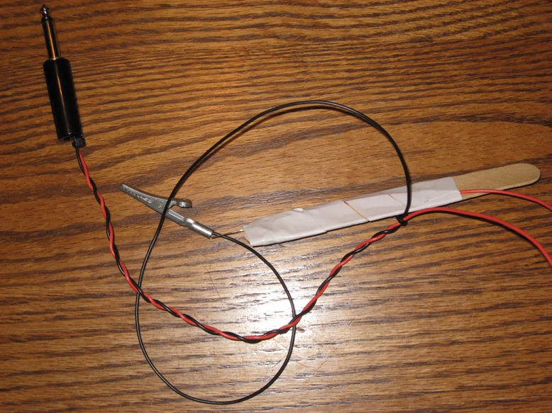 probe.JPG
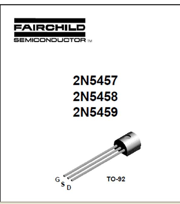 2n5458.jpg