| Author |
 Topic Topic  |
|
|
Dave Simpson
Copper Member
USA
9 Posts |
 Posted - 10/06/2007 : 13:29:00 Posted - 10/06/2007 : 13:29:00


|
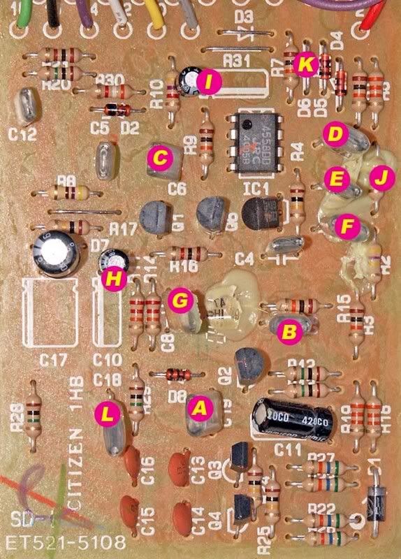
I was modding a brand new Boss SD-1 and the trace came off of the PCB where the R2 resistor is when I was sucking up the solder to remove the resistor.  It was the top hole where R2 is located. My question is where should I jump the resistor lead to? Help!!!!! It was the top hole where R2 is located. My question is where should I jump the resistor lead to? Help!!!!!
R2 is the resistor right under "J"
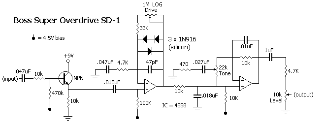
On the schematic R2 is the 470K resistor
 |
|
|
Dr. Bob
Moderator

Australia
6593 Posts |
Posted - 10/06/2007 : 13:58:07

|
Hi Dave Simpson, Christo & Guys
Christo just finished destroying... errrrr, modding his beloved SD-1.
He might have some pics of the back of the PCB to upload & show you.
Christo did the 10,000 component mod , (just Kidding) he was experimenting with every mod "Known to Man" , (just Kidding) he was experimenting with every mod "Known to Man"
I believe that most of the tracks on his SD-1 are still intact.
Or if can upload some pics of the damaged area, from the track side,
we'll help you out, else I have to get one of my SD-1's out of storage to open it up.
I guess I'm just a little lazy - it's Saturday night over here.
Regards Dr. Bob |
 |
|
|
Dr. Bob
Moderator
Australia
6593 Posts |
Posted - 10/06/2007 : 14:33:49
|
Hi Dave Simpson & GUYS
Sorry about the pics guys, I'm having timeout problems when uploading.
I sent the pics to Bossarea, to add to my uploads, so please be patient.
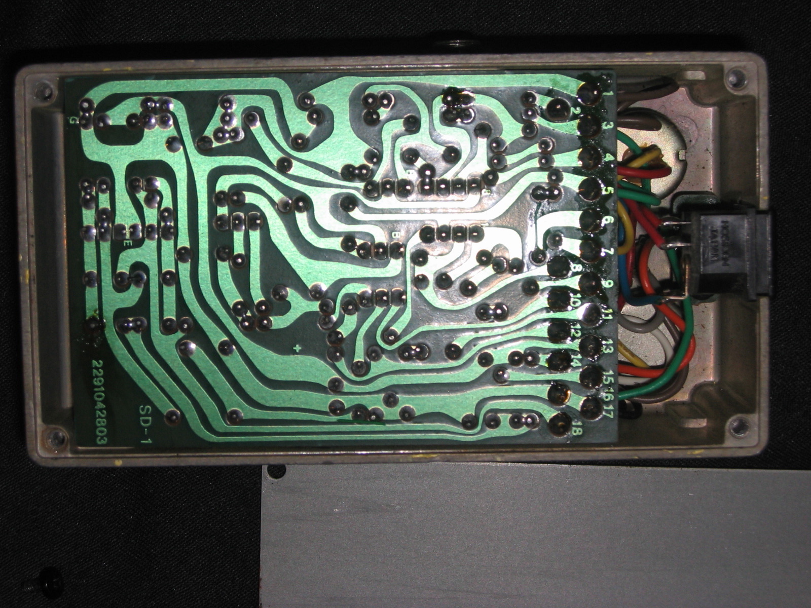
Meantime I uploaded the first file rotated to show the tracks.
Just found these pics I took of one of my older MIJ ACA adapter SD-1's.
I believe the boards are Identical.
You should be able to zoom in to the affected area, I uploaded Hi-Res pics.
Hope it helps.
BTW guys, the very fine green link, on the left, in the first pic,
Is the jumper for converting the 12V ACA pedal
for use with the PSA 9V adapter, it links out,
the low value resistor in series with the other power diode,
in series with the DC input socket
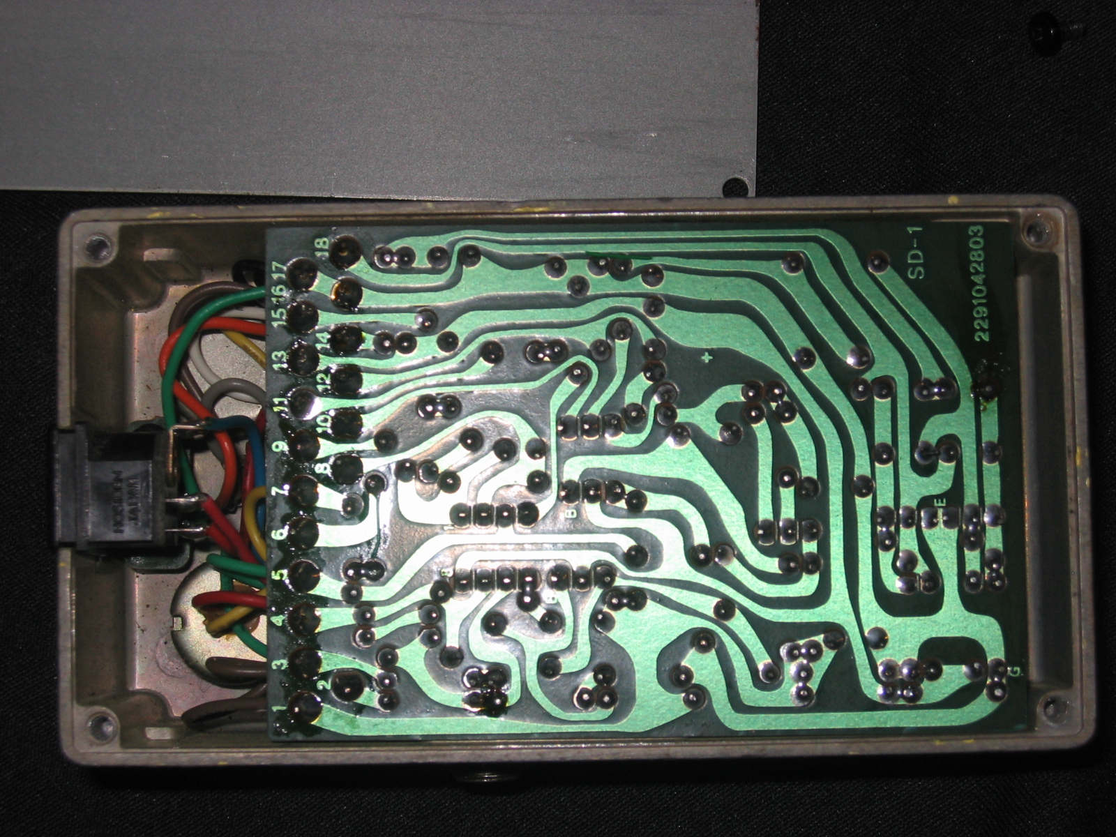
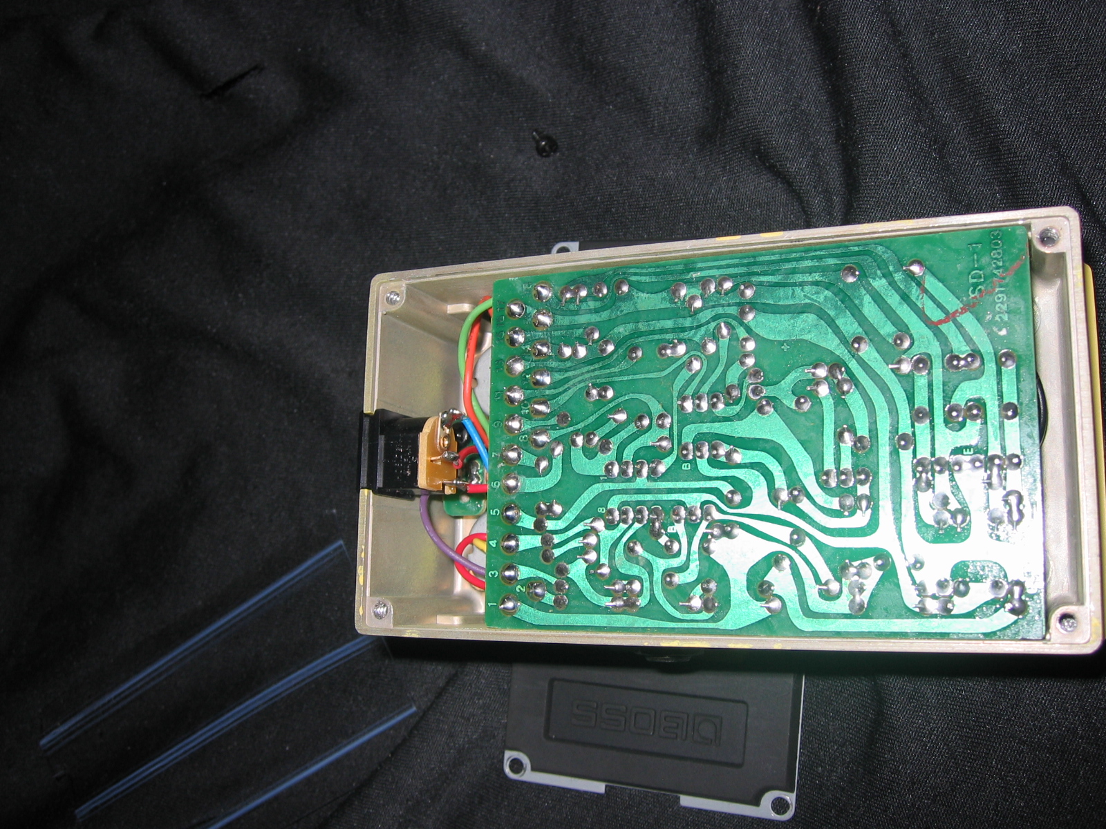
Regards Dr. Bob
|
Edited by - Dr. Bob on 10/07/2007 05:04:51 |
|
|
|
Dave Simpson
Copper Member
USA
9 Posts |
Posted - 10/06/2007 : 15:40:48
|
Bob,here's the damaged area.
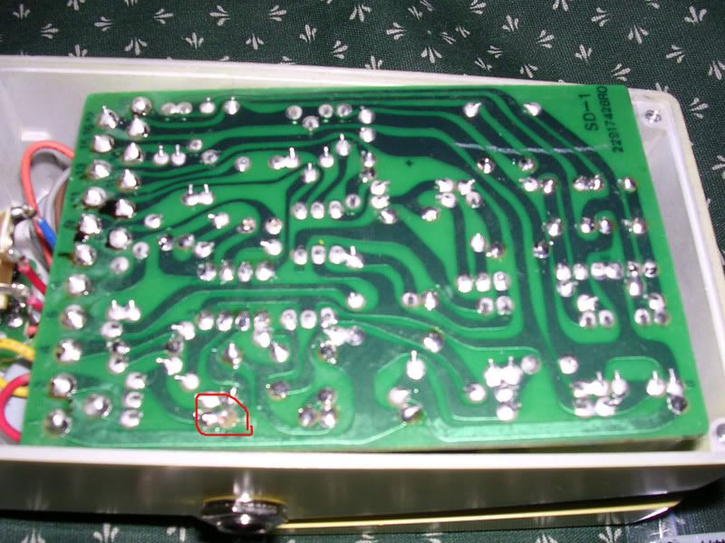 |
|
|
|
Dr. Bob
Moderator
Australia
6593 Posts |
Posted - 10/06/2007 : 16:08:18
|
Hi Dave & Guys
The pics are a bit blurry & don't show enough detail in the damaged area, but.
You can scrape off some of the resist (Green paint over the cooper tracks)
on the track to the right of the damaged area, & run a short wire link from the solder Pads/joints
onto the area that you scrapped clean.
Use the tip of a sharp hobby knife, don't dig in too deep, you just need to get the resist off, & you will see
the bare copper under the green resist.
You can then apply some solder to the copper area that you just cleaned,
And then run the link across to the track from the solder joint/s.
I just noticed, that the solder joint about 2 inches to the right, is not looking too good,
perhaps you should clean it up with some solder-wick & then re-solder it.
Regards Dr. Bob |
Edited by - Dr. Bob on 10/06/2007 16:20:36 |
|
|
|
ChristoMephisto
Platinum Member

Canada
1288 Posts |
Posted - 10/07/2007 : 04:26:28
|
Hey All, sorry, just finished a 12 hour shift
Shouldn't that be the top end of R6? Where the J is. Matches the circled area on the solder side, R2 is rights under it. Hard to tell unless you scrape away the epoxy. The R2 pads look fine.
I can kinda tell the connecting pad, bottom of R5, just above R6 looks good, and thats where the top of R6 connects. An easy fix is when replacing the resistor is to bend it over and solder it to the bottom lead of R5.
In your schem, R6 is the 4.7k res sticking out in series with the 0.047uf cap, and R5 is the 33k connected to the Drive pot.
What kinda mod is that? kinda looks like a TS mod
What does the C18 C19 mods do?
I haven't modded my MIJ SD-1(Bob, i replaced C6) I like the original sound. My MIT one on the other hand...it resembels a ts-808 with a switch to toggle in the D6 diode for clipping options. And I still have a hole to add another toggle for something else. opamp switching?
Don't use it as much since I got my MIJ one for $40.
Bob, 'cause you added some pics, and had to scroll over because the pics were soo big, didn't notice I was looking at two pedals.
Whats the small green wire for at the bottom middle on yours?
Did I mention I have a 21" monitor, your pedals are huge!!!
|
|
|
|
Dr. Bob
Moderator
Australia
6593 Posts |
Posted - 10/07/2007 : 05:03:23
|
Hi Christo & Guys
You asked about the small green insulated link.
I did mention this in the abouve post.
==== Here is the extract. ----
BTW guys, the very fine green link, on the left, in the first pic,
Is the jumper for converting it from the 12V ACA pedal,
for use with the PSA 9V adapter, it links out,
the low value resistor in series with the other power diode,
in series with the DC input socket
I think that resistor is 470 ohms or 330/390 ohms. Mod works great.
===============================
I also managed to email the hi-res pics to Dave in PM,
he said it's sort of, working again, but still sounds a bit weak,
and he will look at it again later, after a bit of a break from it.
Regards Dr. Bob |
Edited by - Dr. Bob on 10/07/2007 05:04:15 |
|
|
|
ChristoMephisto
Platinum Member
Canada
1288 Posts |
Posted - 10/07/2007 : 13:52:38
|
lol, not that wire Bob, the tiny loose piece of insulation on your board
bottom middle of your pic. I did the PSA conversion also, handy considering most of my pedals are mijs.
Dave, double check your mods. Its telling you R6 is R2.
R6+C3 controls your frequency corner/gain. 2k2+.1uf gives you twice the gain with the same midhump sound.
R2 is for the input impedance, they say more is better.
Wondering if the pcbs got cheaper, it took me about 3-4 times soldering the same pad to lift mine, my bad. |
|
|
|
Dr. Bob
Moderator
Australia
6593 Posts |
Posted - 10/07/2007 : 16:29:28
|
quote:
Originally posted by ChristoMephisto
lol, not that wire Bob, the tiny loose piece of insulation on your board
bottom middle of your pic. I did the PSA conversion also, handy considering most of my pedals are mijs.
Dave, double check your mods. Its telling you R6 is R2.
R6+C3 controls your frequency corner/gain. 2k2+.1uf gives you twice the gain with the same midhump sound.
R2 is for the input impedance, they say more is better.
Wondering if the pcbs got cheaper, it took me about 3-4 times soldering the same pad to lift mine, my bad.
Hi Christo
I was hoping no-one noticed it, it's part of the secret
Transwarp Acoustic Coupling Mod, that I have been working on.
It uses the polymer elastomer properties of the insulation, to couple
another 25dB of gain out of that part of the circuit.
Or are you just boasting, cos yours is 21 inches (monitor) 
Or just might be telling you a pile of 
Regards Dr. Bob |
Edited by - Dr. Bob on 10/07/2007 16:30:57 |
|
|
|
ChristoMephisto
Platinum Member
Canada
1288 Posts |
Posted - 10/07/2007 : 16:36:45
|
quote:
Originally posted by Dr. Bob
quote:
Originally posted by ChristoMephisto
lol, not that wire Bob, the tiny loose piece of insulation on your board
bottom middle of your pic. I did the PSA conversion also, handy considering most of my pedals are mijs.
Dave, double check your mods. Its telling you R6 is R2.
R6+C3 controls your frequency corner/gain. 2k2+.1uf gives you twice the gain with the same midhump sound.
R2 is for the input impedance, they say more is better.
Wondering if the pcbs got cheaper, it took me about 3-4 times soldering the same pad to lift mine, my bad.
Hi Christo
I was hoping no-one noticed it, it's part of the secret
Transwarp Acoustic Coupling Mod, that I have been working on.
It uses the polymer elastomer properties of the insulation, to couple
another 25dB of gain out of that part of the circuit.
Or are you just boasting, cos yours is 21 inches (monitor)
Or just might be telling you a pile of
Regards Dr. Bob
Heard they where made from unobtainium, can you hook me up with the schems? |
|
|
|
Dr. Bob
Moderator
Australia
6593 Posts |
Posted - 10/07/2007 : 16:43:07
|
Hi Christo
=== quote ===
Heard they where made from unobtainium, can you hook me up with the schems?
============
Why do you need the schem's? When I uploaded the hi-res pic,
As for the go to:
unobtainium.com/sucker_every_minute.
Scroll to the bottom of page 17.....
Regards Dr. Bob |
Edited by - Dr. Bob on 10/08/2007 09:08:48 |
|
|
| |
Topic |
|
|
|




 Boss SD-1 help!

