| Author |
 Topic  |
|
MervsMods
Bronze Member

USA
133 Posts |
 Posted - 12/12/2009 : 00:16:58 

|
| That's just WRONG in my book. I mod pedals for a living, but that big zit on a boss pedal is W-R-O-N-G !!!! I've had people ask be about true bypass on a Boss, with the 3PDT and I won't do it. Unless you have super sensitive hearing, one can't tell the difference between them. That's like the story about Eric Johnson can hear the difference between a Duracell and an Energizer battery! |
 |
|
|
Scarymonsta
Bronze Member
United Kingdom
90 Posts |
Posted - 12/12/2009 : 14:23:47
|
[quote]Originally posted by Ollie
I thought one of the selling points of the Sd-1 was it's simplicity....
Totally agree 
Even the most extreme mod I do on an SD-1 only puts in two toggle switches and DOES actually give some audible difference in sound.
Didn't Laurie manage an internal true bypass using the existing F-F circuit and a miniature relay? Best way to do it if you ask me.
|
|
|
|
stinkfoot
Silver Member

Sweden
181 Posts |
Posted - 12/13/2009 : 06:34:24

|
If you have to have true bypass (which is a real plus if you have too many Boss/buffered pedals lined up), using a relay is nice. But they tend to draw quite a lot of power, which can make battery use inconvenient. But you can also do this:
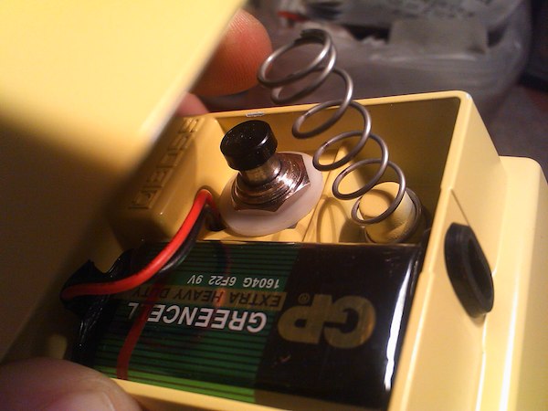
The trick is finding a switch that is small enough to still let the circuit board fit... a regular blue 3PDT won't fit properly, but if you can find one that does, the pedal will look and feel just the same as before.
/Andreas |
Edited by - stinkfoot on 12/13/2009 06:35:32 |
|
|
|
natthu
Gold Member

Australia
756 Posts |
Posted - 12/13/2009 : 07:10:44
|
quote:
Originally posted by DasBeef
I hate to admit it, but those mangled pedals really don't offend me.
I actually think the one in Ollie's video is quite cool. I certainly wouldn't have it done to my MIJ models, but a brand new one. Why not? Might not be a usable pedal for a live situation, but would probably be a fun toy!
I'm not really against modding (I do it myself) nor am I particularly offended... I just think that these 3PDT switches look very amateurish when mounted on the treadle of a Boss pedal... the example shown by stinkfoot looks ok... If you've really gotta have true bypass, then so be it, but atleast try to make it look good! |
|
|
|
Dr. Bob
Moderator

Australia
6593 Posts |
Posted - 12/13/2009 : 13:51:51
|
quote:
Originally posted by stinkfoot
If you have to have true bypass (which is a real plus if you have too many Boss/buffered pedals lined up), using a relay is nice. But they tend to draw quite a lot of power, which can make battery use inconvenient. But you can also do this:
The trick is finding a switch that is small enough to still let the circuit board fit... a regular blue 3PDT won't fit properly, but if you can find one that does, the pedal will look and feel just the same as before.
/Andreas
Hi stinkfoot - Andreas
Any chance you have a picture of the other side (inside) of this pedal, showing the back of the switch?
Nice job BTW.
Regards Dr. Bob  |
|
|
|
stinkfoot
Silver Member
Sweden
181 Posts |
Posted - 12/13/2009 : 16:59:34
|
I don't have any inside pics right now, but I'll see if I can get some. Anyway, it's just a regular 3PDT, but a little smaller/shorter than the common "blue" switch everybody uses. The switch also has a lighter touch than the blue 3PDT, which is nice (although it remains to be seen if that also means it is more fragile =)
The FET switching is disabled (by simply removing the FET transistors and jumpering across the one carrying the "wet" signal) and since the resistor for the LED in the SD-1 sits on the anode side, the cathode simply connects to ground through the switch. Other Boss pedals have the resistor on the cathode side, meaning you have to remove a few components to get a clear connection point - after the resistor - to run a wire to the switch/ground.
On the SD-1, I had to remove C9 to get enough room to close the pedal up, but since that cap is part of the dry/bypass path (which I'm not using anymore) that's not a problem. I just did a TR-2 as well, and in that one there was less room - I ended up having to bend a SIP8 op-amp as far as it could go to one side, and then bend each leg on the 3PDT forwards, before the lid would close properly.
/Andreas |
Edited by - stinkfoot on 12/13/2009 17:13:25 |
|
|
|
Laurie
Double Platinum Member

Canada
4854 Posts |
Posted - 12/13/2009 : 22:44:56
|
| I used the existing flip-flop to drive a sub-mini relay wired in where the FETs used to be. All you need is a PNP transistor and a couple of resistors. THis has the advantage that the LED is still driven by the flip-flop and so you only need a DPDT relay. I used a tiny Panasonic one with a 12mA hold current. Not the best for battery power, but not terrible either. Not an issue with external power. |
|
|
|
stinkfoot
Silver Member
Sweden
181 Posts |
Posted - 12/13/2009 : 23:56:18
|
Relays are like voodoo to me  I have never messed with them, but I know they can be really useful. Good job! 12mA is perfectly reasonable - I've seen relay-based loop pedals where each relay/loop draws 40mA, which is far too much, IMO.
You haven't noticed any issues like the Digitech Hardwire series, where (presumably) static electricity can make the pedals turn on/off when you touch the pedal case?
/Andreas |
|
|
|
stinkfoot
Silver Member
Sweden
181 Posts |
Posted - 12/14/2009 : 00:38:15
|
A Dr. Bob special, coming up :D
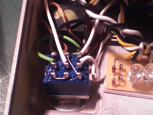
The twisted wires are for the clipping diode switching bit (4x1N4148 / 2xLED / 2xMosfet). The only thing left to do now is to gig-test it for a while, to see that the switch holds up.
/Andreas |
Edited by - stinkfoot on 12/14/2009 00:39:11 |
|
|
|
Alice
Bronze Member
USA
66 Posts |
Posted - 12/14/2009 : 03:16:30
|
Hey Andreas,
Is that a random switch you found in a junk drawer or do you know the make and model to be able to get more of them?
Maybe you should offer this as a mod on select pedals (hint hint)
-A |
|
|
|
stinkfoot
Silver Member
Sweden
181 Posts |
Posted - 12/14/2009 : 04:00:13
|
The switch is a Fujisoku 8Y3011, bought from www.elfa.se. It normally doesn't come with the plastic cap, and on the others (I've done three pedals so far) I've simply used a piece of gaffa tape on the inside of the treadle, to stop it making clunking noises. That works just as well, and as it is a hair thinner than the cap, I can set the switch a hair deeper (giving me - you guessed it - a hair more room for the circuit board).
Fitting it is a chore - I need to file out the cutout for the battery wires a bit, and finding the right height takes a little time (especially since I have to take the treadle off to mount the switch, then put it back to test etc). Also, the switch is about twice as much as a regular blue 3PDT (about �10 instead of %5.50) so it will cost a bit to have it done. But if these three holds up over time (i.e. no switch failures or other weird behaviour) I'll start offering at as an option, yes.
/Andreas |
Edited by - stinkfoot on 12/14/2009 04:03:10 |
|
|
|
Laurie
Double Platinum Member
Canada
4854 Posts |
Posted - 12/14/2009 : 04:50:16
|
quote:
Originally posted by stinkfoot
Relays are like voodoo to me I have never messed with them, but I know they can be really useful. Good job! 12mA is perfectly reasonable - I've seen relay-based loop pedals where each relay/loop draws 40mA, which is far too much, IMO.
You haven't noticed any issues like the Digitech Hardwire series, where (presumably) static electricity can make the pedals turn on/off when you touch the pedal case?
/Andreas
No... I've done two of these and they are both working with no issues. |
|
|
|
stinkfoot
Silver Member
Sweden
181 Posts |
Posted - 12/14/2009 : 16:56:40
|
First switch failure...  I'll have to replace it and try a few more to know if it was a fluke, or if these switches are not to be trusted.
/Andreas |
|
|
|
stinkfoot
Silver Member
Sweden
181 Posts |
Posted - 12/14/2009 : 23:51:07
|
Ok, so the second switch failed tonight... I think it's the angle the treadle hits the switch at that does it - the switch is now sitting almost level, while the treadle comes down at an angle. This not only pushes the switch stem down, but also forwards. Apparently this is enough to make it skip.
So the switch would either have to be mounted at an angle (to better match the angle of the treadle), or I need to rethink the whole thing. Maybe it's time I started messing with the relay voodoo stuff after all... Laurie - I'd love to get some tutoring
/Andreas |
|
|
|
Laurie
Double Platinum Member
Canada
4854 Posts |
Posted - 12/15/2009 : 00:24:46
|
quote:
Originally posted by stinkfoot
Ok, so the second switch failed tonight... I think it's the angle the treadle hits the switch at that does it - the switch is now sitting almost level, while the treadle comes down at an angle. This not only pushes the switch stem down, but also forwards. Apparently this is enough to make it skip.
So the switch would either have to be mounted at an angle (to better match the angle of the treadle), or I need to rethink the whole thing. Maybe it's time I started messing with the relay voodoo stuff after all... Laurie - I'd love to get some tutoring
/Andreas
Happy to help! It was a bit of a black art to make it work the first tme, but I have it sorted out now. I'm on vacation at the moment, but in the New Year I will have access to my schematics and notes - will ping you then.
|
|
|
|
Topic |
|




 True bypass Boss pedal mod


