| Author |
 Topic Topic  |
|
happyplucker
Bronze Member

United Kingdom
126 Posts |
 Posted - 02/27/2008 : 19:41:36 Posted - 02/27/2008 : 19:41:36


|
hello,
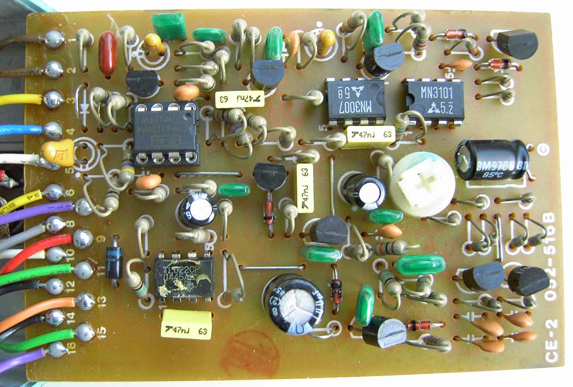
i have previously posted an issue regarding my CE-2. i described it worng however, so now im at home im going to take my time and add a picture to help myself more than you guys coz you know your stuff!
basically i modded it about 2 years ago with the monte allums mod. and it worked great. in the last week or two though the effect will not come on (although the light shows on and off) and there is a strange, clicking noise that fluctuates with the rate knob, so if i turn the rate knob up it goes faster and vice versa.
if anyone has any idea what this is and how to fix it please let me know. and i've added a picture if a few components need replacing, feel free to circle them so its easy for a novice like me to understand! i have a picture of the back if anyone needs it.
thanks in advance guys.
 |
Edited by - Dr. Bob on 06/21/2008 19:06:05 |
|
|
ssanyee
Silver Member

Hungary
288 Posts |
Posted - 02/27/2008 : 20:41:32
|
Hi happyplucker,
Waht about in bypass mode? Is it working?
What parts did you modified years before (as I can see only 47nF caps)?
Do you have schem? Based on what you made the mod?
Solderings are OK?
What about the DC measurements in the legs of ICs?
These questions have to be answered at first and afterwards go away!
Nice picture anyway  ! !
cheers  |
Edited by - ssanyee on 02/27/2008 20:43:06 |
 |
|
|
ChristoMephisto
Platinum Member

Canada
1288 Posts |
Posted - 02/28/2008 : 00:54:02
|
All I can see is the electro caps were swapped out for tantiums, input cap upgraded, the 4558 to a 4213 dual op amp, and speedy mod, and the PSA conversion. What are the box caps for?
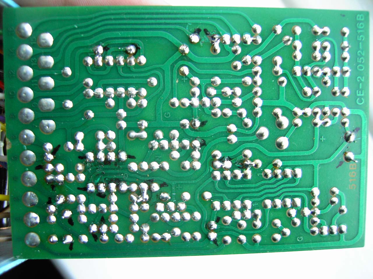
What does the solder side look like? Any burns, shorts or opens?
Are those two resistors to the left of the TL022 touching?
|
|
|
|
Dr. Bob
Moderator

Australia
6593 Posts |
Posted - 02/28/2008 : 06:37:40

|
Hi happyplucker
Dito with Christo & ssanyee
We probably need to see a pic of the solder side as well.
You mentioned that you are somewhat of a novice to all this.
SOLDERING IS VERY INPORTANT...
And maybe some leads are touching on the back of the PCB.
Regards Dr. Bob |
|
|
|
happyplucker
Bronze Member
United Kingdom
126 Posts |
Posted - 02/28/2008 : 10:26:56
|
cool. guys, i have the parts i replaced at home, which i'll copy out when i get home. and i have a pic of the solder side, which i'll upload when i get home.
in bypass mode, i presume when its turned off, the clicking noise is there, and the guitar signal is there an unaltered, when the pedal is turned on, the clicking noise remains, the effect is NOT present, but the guitar remains the same.
like i said, i am a novice to all this so hopefully i wont annoy any of you too much.
hopefully my soldering is ok. until later, thanks for your help thus far. :)
oh i ve also got another question about an sd-1 which i recieved in a semi altered state. but thats for another time! |
Edited by - happyplucker on 02/28/2008 10:37:02 |
|
|
|
happyplucker
Bronze Member
United Kingdom
126 Posts |
Posted - 02/28/2008 : 18:14:06
|
ok guys, here's the back.... hopefully something stands out! btw, those two resistors were not touching  ( ibet you guys would be embarrassed to post such shoddy soldering)! ( ibet you guys would be embarrassed to post such shoddy soldering)!
 |
Edited by - happyplucker on 02/28/2008 18:28:32 |
|
|
|
RonNovy
Copper Member
USA
24 Posts |
Posted - 02/28/2008 : 20:05:11
|
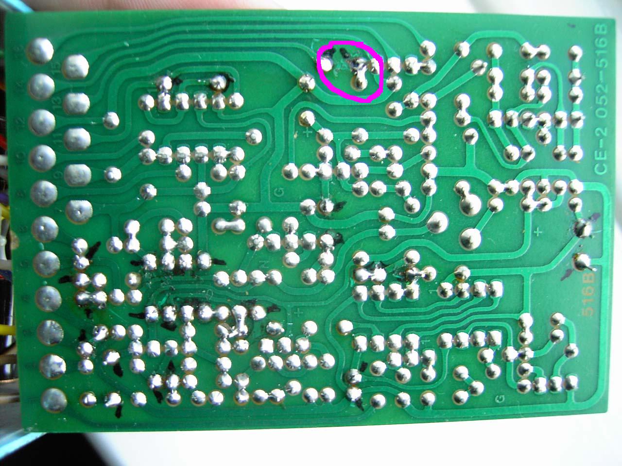
Make sure the IC is in the socket and that all pins are making contact, then check the POT's.
Oh and you might want to check the solder point I circled in purple here:
 |
|
|
|
Laurie
Double Platinum Member

Canada
4854 Posts |
|
|
happyplucker
Bronze Member
United Kingdom
126 Posts |
Posted - 02/29/2008 : 11:45:48
|
| ok, i looked and re did that solder joint. still no different. thanks for the shcematic but it wont be much use to me, but maybe it'll help some of the more experienced people. still unsure as to why it would just stop working after a year or two though, surely if it was sodlering it would have happened at the time of the mod? |
|
|
|
ChristoMephisto
Platinum Member
Canada
1288 Posts |
Posted - 02/29/2008 : 12:21:48
|
Did you check the components with a meter?
The only thing I can think of is a comp went south.
Is it possible your brown burr op amp to be switched out for a 4588?
good luck |
|
|
|
happyplucker
Bronze Member
United Kingdom
126 Posts |
Posted - 02/29/2008 : 12:27:40
|
i may have another opamp spare, if i do , ill give it a switch around tonight, and see if it makes the clicking stop... cheers!
btw, using a meter, am i using it in exactly the same way i would use it on say testing guitar electrics and such like, and what would be the first components i should check? |
Edited by - happyplucker on 02/29/2008 12:29:50 |
|
|
|
ChristoMephisto
Platinum Member
Canada
1288 Posts |
Posted - 02/29/2008 : 12:49:00
|
| Check the comps you modded first, then using the continuity test(beep!!) check to see if all the contact and leads are closed. |
|
|
|
happyplucker
Bronze Member
United Kingdom
126 Posts |
Posted - 02/29/2008 : 18:04:47
|
| cheers christo, and you answered in language even i can understand! I'll set myself and hour ro two tonight and do it... let you know how it goes. |
|
|
|
happyplucker
Bronze Member
United Kingdom
126 Posts |
Posted - 02/29/2008 : 22:26:30
|
tried changing the opamp, no difference, and have continuity tested the components i have put in, and they all seemed ok, well, as far as i can say... will try the rest of the components, when i have some more hours free. |
|
|
|
RonNovy
Copper Member
USA
24 Posts |
Posted - 02/29/2008 : 23:37:54
|
Did you continuity test all the wires and the pot controls on the box as well?
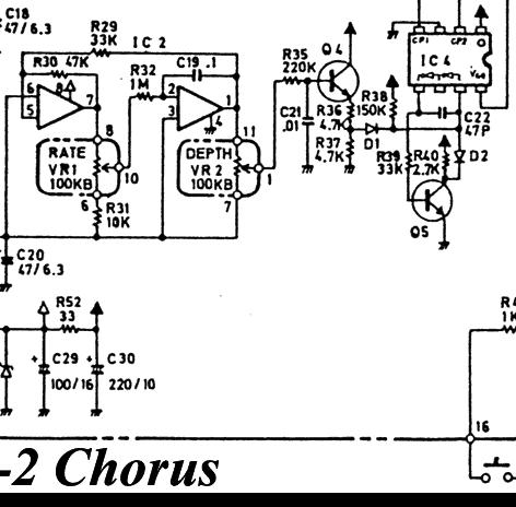
Edit: Ok I've looked up the other chips and if its not the wires or the pots then I think you might find the problem near the MN3101 or MN3007. They create the delay for the chorus effect. Here is a close up of the MN3101 in the schematic. The MN3101 generates the clock pulses that the MN3007 needs to create the delay effect. I believe the clicking noise is because of a bad clock pulse going into the MN3007 or the MN3007 itself is bad. If you replaced any caps connecting to this circuit then change them back. This part of the circuit is not audio so it won't directly affect the sound and could cause the clock rate to become too fast for the MN3007. Hope this helps  Also check C9. Also check C9.
Edit: Sorry another edit...
A way to check Q9 (be sure its Q9 before trying) is to short the side connecting to the 47k resistor and the side connecting to IC1. If there is no more clicking and you get a chorus sound from that test then check D4 (and D8) Diodes should have continuity in one direction but not the other, but of course you knew that. If D4 and D8 are good then of course Q9 would be bad... |
Edited by - RonNovy on 03/01/2008 02:06:17 |
|
|
|
happyplucker
Bronze Member
United Kingdom
126 Posts |
Posted - 03/01/2008 : 16:07:49
|
| great. and just to clarify for a novice, how exactly to short something out... if thats ok and if you want to be really specific, could you mark the bits on the picture of the pcb? that would be ace? |
Edited by - happyplucker on 03/01/2008 16:11:26 |
|
|
|
Topic |
|