quote:Originally posted by copper Do you mean how they are wired or what direction the lugs are facing? Elaborate on your question.....
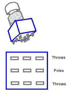
yes both..how they are wired adn which directio the lugs are facingi have a picture of an A/B switch im building i got online..the website isnt on the print out..i can find it though
i figured i would find this out before i started soldering
I hope you have a digital multimeter or something to measure resistance because that would really help.
take the 3DPT and connect one of your meter connectors to the center tip. now measure the resistance in all directions north, east, south and west. you'll find that only for one of the directions you will get zero resistance. thereby you can tell that the switch moves in that direction. for example:
Center to north 0 resistance, switch, center to south zero resistance Center to east 0 resistance, switch, center to west zero resistance
I hope that explains enough, you'll have to figure out from that which way the schematic you have wants it.
Well when you know which tips connect when you swith that tells you how to wire it.
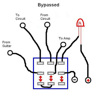
You put the 3DPT down and switch and make sure that the zero connection is switching between middle to up and middle to down. which will be the same as most the diagrams that defrag posted. you can then wire them like that or like the original diagram. you can hold it up infront of your computer screen if it helps.
In general i would say that most schematics have the switching between middle and upper side and middle and lower side. thought you might come across some that are different.
If your schematic has a led on it this is usually the easiest place to detect which way around it should go, as the current should either flow or not flow at all.