|
RonNovy
Copper Member
USA
24 Posts |
 Posted - 04/01/2008 : 07:49:41 Posted - 04/01/2008 : 07:49:41


|
Ok.. I've drawn up a schematic of this old beat up PSA adapter and its the same as my diy powersupply (except for some additions), but I'm curious to know what the ACA power adapter looks like on the inside. Does anyone have a schematic or any information on the internals of the ACA adapter? Is the unregulated ACA just a transformer or are there some diodes to form a bridge? What is the transformers secondary voltage rated?
Arg... I can't find a schematic anywhere and I've never even seen one of these ACA power adapters, but here is what I have guessed.
Transformer: ~6.3VAC out (9/1.45=6.206) or ~8.3VAC (12/1.45=8.276)
Diodes: 4x 1n4001
Fuseing: diode rated around 200ma?
Can anyone tell me if I'm even close?
Anyway here is the schematic for the PSA-120T if it helps.
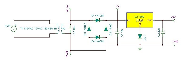
I didn't test the AC Volts from the transformer but it should be equal to or slightly greater than 6.3VAC.
|
Edited by - RonNovy on 04/01/2008 08:36:44 |
|