is a chinese ce 2 collectible? Is any chinese pedal collectible?
People in Taiwan might take exception to that.. I usually classify Taiwanese construction well above Chinese - especially when drien by a Japanese company.
The PQ-4, PN-2 and FZ-3 are pretty collectible for MIT pedals. Any CE-2 is worth a buck or three.
quote:Originally posted by ironman28 What if there were a way to TB a Boss pedal without drilling, cutting or otherwise modding it in a way that is not reversible?
There is - it uses a latching relay, driven by the flip-flop. Bit fiddly and a bit expensive, but it's just soldering of wires and is 100% reversible.
that was a rhetorical question... I've found that a relay based circuit is about $5 (USD) in parts about the same as a 3PDT footswitch. For non battery power you can go with a non-latching relay. I like idea of 'stealth mods" where the thing looks stock but under the hood...
quote:Originally posted by ironman28 I've found that a relay based circuit is about $5 (USD) in parts
Is this for a latching relay solution? The best I've found is about $15 for parts and a small PCB - need a latching relay ($7) and a 556 dual timer and a few associated components plus a board to mount it on. The 556 is used to one-shot pulse the relay so that the coil doesn't remain energised (no point using a latching relay if you leave it energised...).
If you have a simpler method, I'd be really pleased if you could share it!
The non-latching relay solution is easier, but draws more current. I usually use a driver transistor off the effect board so the flip-flop balance isn't affected by the relay coil load.
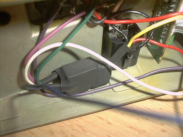
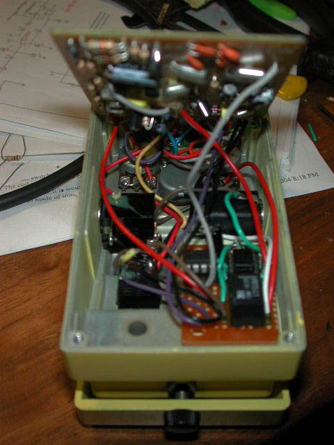
I originally used a high sensitivity 3VDC non-latching relay with a 2N7000 MOSFET driving the coil. A series resistor and clamp diode completed the circuit. I assembled these on perfboard and enclosed them with heat shrink. The package was small enough for most pedals. The additional current draw was 10ma when engaged The guys over at diystompboxes have come up with some variations using dual coil latching relays.
$3 for the relay and maybe a $1 for the cap and 4049. I have decided that a PCB is over kill and have built several "deadbug" style then enclosed with expoxy/heatshrink to minimize the foot print. If you use a different relay you may need to parallel two of the inverter sections. You may also need to increase the 4.7uf to 10uf. Use a tantalum here to save space. The one advantage of the nonlatching relay is it will always fail to the bypass position if power to the pedal fails. Let me know if you need a couple of relays to test
The latching ones don't draw any current when latched (of course!) and cost about $7, but the drive circuit for them (converts continuous 9V from the flip-flop to a 100ms pulse to drive the coil) is only in the design stage right now.
Laurie- Try the 4049 inverter circuit, it works very well. Because it works by charging/discharging the cap the coil current ramps up relatively slowly the coil pluse noise is eliminated. The CMOS inverter has intrinsic diode protection on the outputs also. The unused inverter sections could be used to implement a complete flip flop ala DOD so the circuit could be used with any momentary switch.