| Author |
 Topic Topic  |
|
|
Dr. Bob
Moderator

Australia
6593 Posts |
 Posted - 08/09/2008 : 16:45:00 Posted - 08/09/2008 : 16:45:00


|
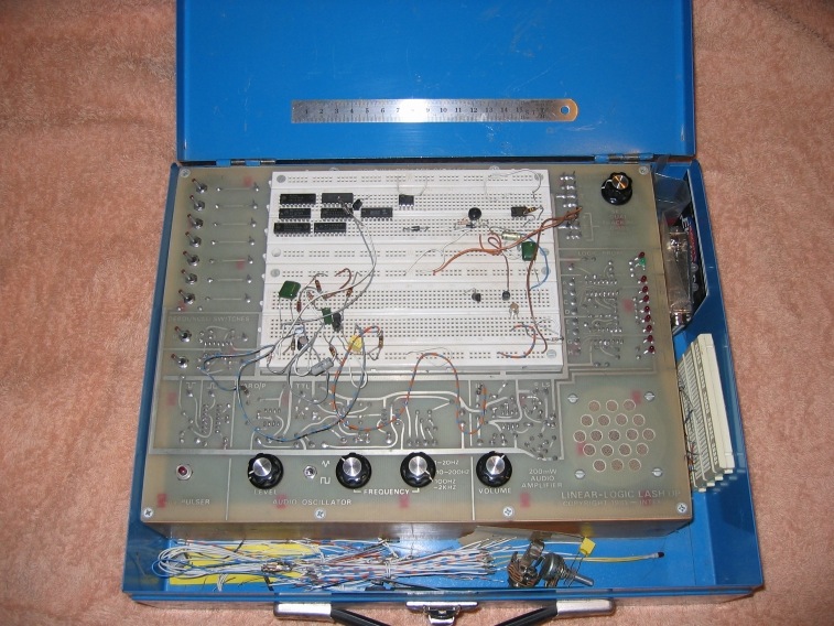
Hi Guys
As requested by "the-destructor" & a few other in PM.
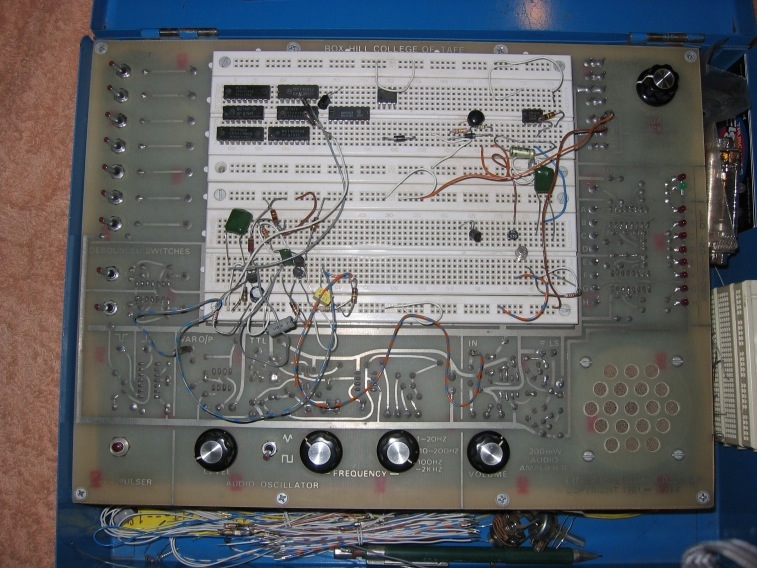
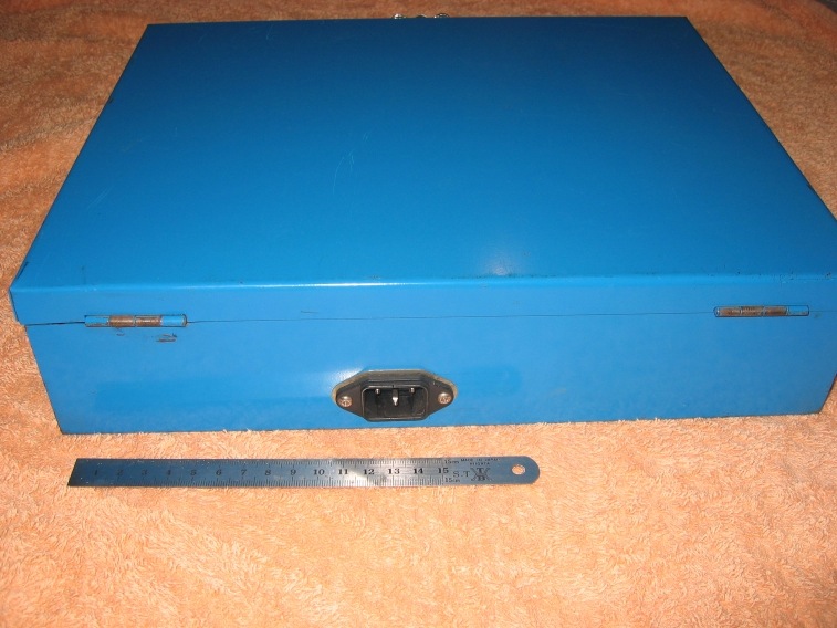
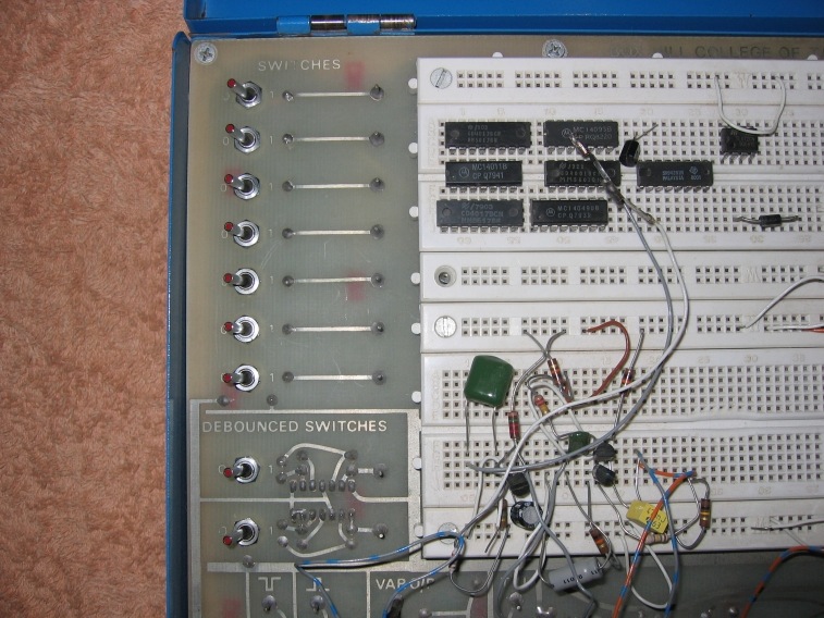
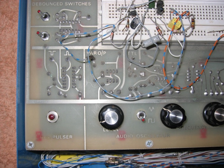
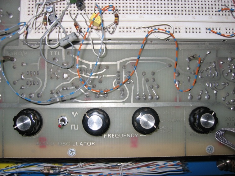
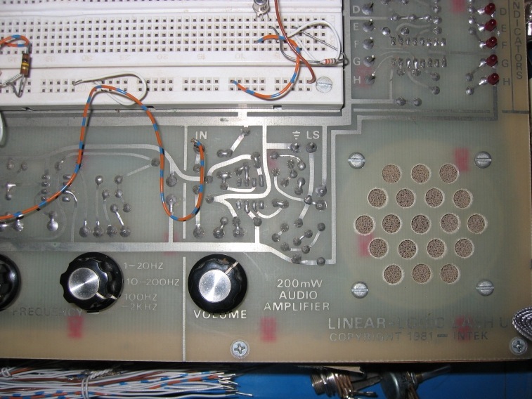
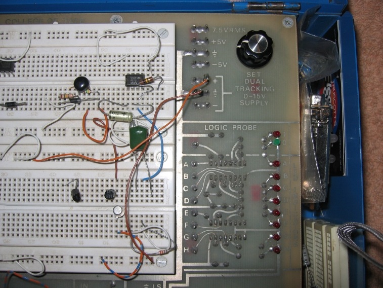
Here are the pictures of my "Linear & Logic Lash Up Breadboard" with built in test gear & power supplies.
I Made a seperate thread so as not to hijack Laurie's thread, on his fine prototype "Looper Mixer" pedal:
http://www.bossarea.com/forum/topic.asp?TOPIC_ID=5002
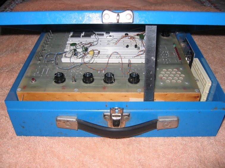
As you can see from the pictures it's basically built on a large piece of upside-down (PCB) Printed Circuit Board.
It sits on an internal frame of polished Tasmanian Pine,
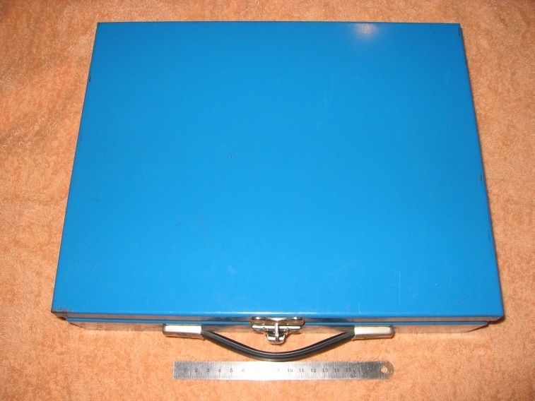
which I then fitted into a Blue metal hinged case, that was fro a power drill, I purchased the case at a Sunday market.
The case also keeps out, damaging house dust & dirt, from infiltrating the breadboard sockets.
I fitted an IEC (jug-kettle) socket to the outer case, so that it's a neat all in one box.
And like Laurie, I cut & stripped many meters/feet of single core solid tinned copper telephone cable, for the assorted jumpers.
If you look close enough you might even see the approximate date, that it was made-designed
As Laurie & other Tech types will attest, the costliest part of the whole project, were the two large high quality interlocking breadboards.
I have placed a small 150mm (6") engineering rule, in some pictures as a scale reference.
Regards Dr. Bob
|
|
|
Laurie
Double Platinum Member

Canada
4854 Posts |
Posted - 08/09/2008 : 16:47:45
|
You are a freakin super techie Dr. Bob!! I am VERY jealous  |
 |
|
|
Dr. Bob
Moderator
Australia
6593 Posts |
Posted - 08/09/2008 : 17:06:42
|
quote:
Originally posted by Laurie
You are a freakin super techie Dr. Bob!! I am VERY jealous
Hi Laurie & Guys
Thanks for your kins comments Laurie.
I am very proud of my Lash Up board, & where possible, I really try to take care of tools, equipment & test gear.
The only thing that ever happened to it, was one of the tantalum caps
on the the positive rail, of the tracking variable supply went dead short circuit.
It was the first time I had encounter a shorted tant., & I will admit, it had me scratching my (then not so old) noodle.
I over-engineered the internal heatsinks, to ridiculous size, & I guess I was lucky I did, as they got REALLY (explicative) Hot, while I was trying to track down the fault.
In the other thread on your looper-mixer, you wrote you got yours breadboard for $10, including a shoebox full of components.
Now that's a really good price.
Mine was a tad costlier, & consumed a quite a few hours of time to construct & house.
I used a metal case (it's painted mild steel, not aluminum) for shielding,
as well as protection, & I did ground the case.
Regards Dr. Bob
|
Edited by - Dr. Bob on 08/09/2008 17:09:25 |
|
|
|
Laurie
Double Platinum Member
Canada
4854 Posts |
Posted - 08/09/2008 : 17:15:32
|
| I'll say it again... I am very jealous!! This is a fantastic rig! (and you know I know exactly how much work went into making it...) |
|
|
|
DeFrag
Moderator
USA
3409 Posts |
|
|
Dr. Bob
Moderator
Australia
6593 Posts |
Posted - 08/10/2008 : 06:17:55
|
Thanks DeFrag.
I really liked that Beavis Audio pedal breadboard.
Any chance you might have had some input into it's design.
It's a really great idea, & I will admit, my heart fluttered a bit,
when I went to the link that you posted, many months ago.
It was a different time & for a different purpose, them I built mine. (did you spot the date?)
Over the years, I have added a small L-shaped aluminum bracket with a few 6mm - 9mm - 12mm holes to hold a few pots-switches & input/output sockets & plugs.
The Beavis Audio is a nice design, but it needs a faster way to connect things to the buss-connector blaocks.
I have had a bit of flash about what's going to be added to my lash-up board next.
Regards Dr. Bob
|
|
|
|
the-destructor
Silver Member

USA
334 Posts |
Posted - 08/10/2008 : 12:39:33
|
Hi Uncle Bob,
Yes - I'm imposing the highly unwanted & unanticipated adoption upon you. That is WAY COOL. That looks like it took a little well-thought out planning on it's own. I'm truly impressed. Nice work!!!
Regards & cheers & cheers , ,
T-D |
|
|
|
Dr. Bob
Moderator
Australia
6593 Posts |
Posted - 08/10/2008 : 15:41:18
|
quote:
Originally posted by the-destructor
Hi Uncle Bob,
Yes - I'm imposing the highly unwanted & unanticipated adoption upon you. That is WAY COOL. That looks like it took a little well-thought out planning on it's own. I'm truly impressed. Nice work!!!
Regards & cheers,
T-D
Hi the-destructor
I gather that may, or may not be a good thing .... dad
It's part of the engineering job that I used to have, prior to my current Technical Specialist position.
You could build a similar project & mount it all to a sheet of plexi/perspex or onto aluminium, buy building all the seperate bits of gear on some veroboard-stripboard.
If I was to rebuild it, I would use an aluminium sheet with some nice labeling, plugs & sockets.
I like the idea behind the Beavis Audio design, but it's not practical for me.
I still have a few goodies, but I'll keep them up my engineers sleeve for now.
Regards Dr. Bob
3333 |
Edited by - Dr. Bob on 08/10/2008 15:42:05 |
|
|
|
Laurie
Double Platinum Member
Canada
4854 Posts |
Posted - 08/10/2008 : 16:33:45
|
quote:
Originally posted by Dr. Bob
I gather that may, or may not be a good thing .... dad
Be afraid Dr. Bob... be VERY afraid |
|
|
|
pawnshop_trash
Gold Member

USA
603 Posts |
Posted - 08/14/2008 : 19:46:36
|
wow! 
kudos Dr. Bob, that's some niiiice work. but what exactly is a 'debounced' switch? 
|
|
|
|
DeFrag
Moderator
USA
3409 Posts |
Posted - 08/15/2008 : 00:22:49

|
| When you move an SPST switch in a switch circuit from ON to OFF or from OFF to ON, the resulting output bounces around between low and high voltages for a short time. If the switch circuit output is used as a synchronizing signal (such as a clock) in a digital machine, weird things will happen. If the machine is a counter, the count may seem to jump wildly. This is obviously undesirable, so a debouncing circuit must be built using a SPDT where the center pin is connected to one or the other of the outside pins, depending on the position of the switch... |
|
|
|
Laurie
Double Platinum Member
Canada
4854 Posts |
|
| |
Topic |
|
