| Author |
 Topic Topic  |
|
Laurie
Double Platinum Member

Canada
4854 Posts |
 Posted - 02/25/2008 : 10:03:16 Posted - 02/25/2008 : 10:03:16


|
G'day!
I've been using the power supply in the attached schematic to power pedals for about 3 years now (I've built six so far). It is the "standard" form of power supply for 78XX style regulators (from the spec sheet). It works with no problems powering my eleven assorted pedals (analogue and digital, Boss and others).
Total cost was about $20. The 15VDC 1000mA "wall wart" that I use to drive it was bought at a thrift store for $1 - I think it's from a printer.
Notes:
1) The high output blue LED is optional. If you use a normal LED, change the resistor from 2k2 to 560 ohms (I used 2k2 resistor with the high output blue LED because with a 560 ohm resister, it was blinding... use a 560 ohm resistor if blinding floats your boat!). A LED should be used - the 7809 regulator needs a small load if there are no pedals plugged in, plus it tells you if the supply is actually working.
2) The bridge rectifier could be a 5 amp type if you want the whole thing to be more robust (but more expensive). I have built three of these now with the 1 Amp bridge and haven't had any problems.
3) The 7809 *must* be bolted to a heatsink (preferably aluminium, preferably at least 10 square cm in size) and heatsink compound *must* be used. The metal tab on the 7809 is at "ground" potential, so be careful with ground loops - you can use a mica washer isolating kit if you are having trouble.
4) The 1000�F and 10�F capacitors are "electrolytic" type. Higher voltages are OK, but they will be bigger physically.
5) The 0.1�F capacitors are "metal film" type. Higher voltages are OK, but they will be bigger physically. I just used some 25V ones I had in the junk box. These capacitors should be as physically close to the 7809 as possible - I soldered mine directly to the leads of the 7809.
6) To be completely safe, a fuse should be added before the bridge rectifier (1 amp slo-blow). I've never bothered because of the extra cost and haven't had problems so far.
7) To get the power to the pedals, I bought some old cheap "plug packs" at the thrift store, cut the leads off them and joined the leads all to the 9VDC output (a sort of octopus coming out of the power supply). You could also buy new connectors from the electronics store and build a chain. Be careful with polarity... center of the connector is negative/ground.
THIS INFORMATION IS PROVIDED FOR THOSE WHO WANT TO EXPERIMENT. IT IS PROVIDED WITH NO WARRANTY OF ANY SORT...
 |
Edited by - Laurie on 02/03/2009 02:47:58 |
|
|
Dirk
Platinum Member

Netherlands
1309 Posts |
Posted - 02/26/2008 : 16:52:21
|
That's pretty much what I build to power my old board.
But I'd copy it 5 times, to power each pedal separately so the outputs are isolated from each other and it doesn't hum.
You can get away with a single rectifier and the first big capacitor, I use a 2200 uF and split it out from there.
I would also replace the 7809 with an 7812 to power old style ACA pedals, this works like a charm.
Btw, I never used a heatsink and never had any problems with overheating, plus I had 5 of 'em in a closed case. |
 |
|
|
Laurie
Double Platinum Member
Canada
4854 Posts |
Posted - 02/26/2008 : 17:00:30
|
G'day Dirk!
Yep, a heatsink isn't required to power one pedal. To pull the whole 1000mA out of it you do need one though... 
I haven't had any issues with hum - the trick I've found is to use a "star topology" to distribute the power (one cable per pedal, all connected together at a central point), rather than the usual daisy chain. One 78XX per pedal works too!
Glad to hear someone else has had the same success with the approach!
Laurie. |
|
|
|
stinkfoot
Silver Member

Sweden
181 Posts |
Posted - 02/26/2008 : 22:52:01
|
Dirk - if you run 5 separate voltage regulators off the same DC supply, the ground will still be common for all outputs, right? To get fully isolated outputs, you need to use a multi-tap transformer and keep everything separate (rectifiers/filter caps/regulators) from that point on.
Or am I delusional :D
/Andreas |
|
|
|
Laurie
Double Platinum Member
Canada
4854 Posts |
Posted - 02/27/2008 : 00:07:17
|
Seems right on to me Andreas! What running multiple regulators all from the same transformer (single winding) does do is ensure a common ground point and a "star" topology for the DC which is really beneficial for hum anyway.
Laurie. |
Edited by - Laurie on 02/27/2008 00:07:49 |
|
|
|
RonNovy
Copper Member
USA
24 Posts |
Posted - 02/28/2008 : 11:56:24
|
Hey... I'm new to this forum and have a few questions... I have built my own power supply years ago and recently switched the cable to a daisy chain style cable to get more length out of the cable I have and the hum is horrible!
Would adding a capacitor to each end or just the vary end of the cable cut the hum or am I better off switching it back to the star configuration?
I'm also using a 7812 instead of the standard 7809. Are there any 9v pedals that can't handle the ~11 to 12 volts? The reason I ask is because I know the digital delay has trouble when it is the only pedal plugged in. It won't even turn on if no other pedal is plugged in and turned on, but was curious if anyone else had similar problems...
|
|
|
|
bossarea
Forum Admin

United Kingdom
3652 Posts |
Posted - 02/28/2008 : 12:14:48
|
Hi RonNovy and welcome to the forum.
It shouldn't matter which end of the daisy you connect the capacitor. There's no other components between these points so the beginning and end of the daisy is really the same location.
Using a 7812 is risky business. The pedals are quite robust and will usually not get damaged but there's no guarantees.
|
|
|
|
RonNovy
Copper Member
USA
24 Posts |
Posted - 02/28/2008 : 13:09:47
|
Erg... I'm sure most of the analog pedals would function nicely at 12v, but I guess it really should be 9v as that's what the digital ones will no doubt expect. Time to break out my soldering iron and make some mods...
For anyone who cares here are some notes on pedals I've used at 12v and the schematic I used for my power supply...
DS-1 All anolog circuit functions fine
MT-2 All anolog circuit functions great ;) Used two in parallel too.
DD-3 Digital has trouble with 12v, but can function (Not recommended)
HR-2 Works. LED Shines brightly though... Fun to use on Halloween ;)
I should probably note here that I am now modifying the circuit to use 9v instead of 12v as it is not recommended to use 12v for most pedals. I only included the information here for reference. |
|
|
|
Dr. Bob
Moderator

Australia
6593 Posts |
Posted - 02/28/2008 : 13:14:59
|
Hi RonNovy & guys
Welcome to the forum from Australia.
Be aware that a lot of the digital pedals, starting way back at the DD-2 and DD-3 days have an on-board secondary LM79L05 100mA 5VDC regulator in a small transistor T092 package.
The 78L05 drops th in coming 9VDC to 5VDC for the 5 Volt digital logic parts of the circuit.
Remember that this little regulator is has to dissipate the 9V minus the 5V = 4V as heat.
Now if you are running 12V into it, it's then 12V-5V = 7V so now the poor little regulator has to dissipate 7V as heat, as well as supply the whatever milliamps the pedal requires.
These little 70L05's do not have a heatsink.
So as the other have stated, be careful, as 78L05's are easily damaged.
You could always run a normal 7809 after the 7812, for the pedals that run on 9V
If you can't get a 7809 then use a LM317T programmable reg, you only need to set it up with 2 resistor, or make it variable with a small trim pot.
Or do as I do when I'm really stuck, use a standard 7805 & jack up the common-ground pin with a small resistor bu 4 volts & you will have a 7809 or whatever you jack up the common pin with.
Hope this all makes some sense & helps you out.
Maybe lauries2, Christo & the other guys have other suggestions?
Regards Dr. Bob |
|
|
|
Dr. Bob
Moderator
Australia
6593 Posts |
Posted - 02/28/2008 : 13:18:04
|
Hi RonNovy
I forgot to ask.
Can I ask what Application you used to draw your schematic?
Regards Dr. Bob
|
|
|
|
DeFrag
Moderator
USA
3409 Posts |
Posted - 02/28/2008 : 16:24:52

|
quote:
Originally posted by Dr. Bob
Can I ask what Application you used to draw your schematic?
Regards Dr. Bob
I'd like to know as well. Welome to Bossarea RonNovy!  |
|
|
|
Laurie
Double Platinum Member
Canada
4854 Posts |
Posted - 02/28/2008 : 17:20:27
|
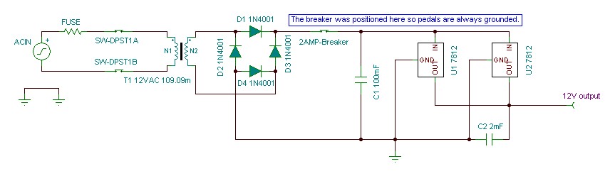
G'day RonNovy! I noticed on your schematic that the two 7812's are directly in parallel. Have you had any trouble with that? If the output voltages are slightly different, one regulator might be trying to "drive" the other? (wasting current/heat) Just thinkling out loud...
Laurie |
|
|
|
RonNovy
Copper Member
USA
24 Posts |
Posted - 02/28/2008 : 19:04:53
|
quote:
Can I ask what Application you used to draw your schematic?
I used TINA-TI from the Texas Instruments website. It's a free windows application and it's pretty powerful, but doesn't have all the BOSS parts I'd like for doing simulations. It's missing some of the transistors and other parts (like the Mitsubishi VCA in the NS-2), but thats ok by me ;) I'm sure someone could create a macro or something...
Here's a link:
http://focus.ti.com/docs/toolsw/folders/print/tina-ti.html
quote:
Or do as I do when I'm really stuck, use a standard 7805 & jack up the common-ground pin with a small resistor bu 4 volts & you will have a 7809 or whatever you jack up the common pin with.
Hmm... Do you have a schematic of how that works ?
quote:
G'day RonNovy! I noticed on your schematic that the two 7812's are directly in parallel. Have you had any trouble with that? If the output voltages are slightly different, one regulator might be trying to "drive" the other? (wasting current/heat) Just thinking out loud...
Actually, I'm not sure. I just threw that schematic together from memory so it might not be accurate. I guess since I'm gonna be rebuilding it I could draw up a more accurate schematic too ;) When I originally designed the power supply it was meant for something completely different, but I modified it a bit for pedal power. I might have separated the 7812s by putting a coil on each output, but I don't remember... Either way I think they only vary by a few millivolts so it shouldn't be that big a deal right?
I know the 7812s are both on the same heat sink though and don't heat up at all... They stay cool unless I'm testing the breaker by shorting the cable, and amazingly even when short circuited they never seem to burn out (I tried to break it! Really I did!) The breaker kicks in before it can even burn my finger. |
|
|
|
Laurie
Double Platinum Member
Canada
4854 Posts |
Posted - 02/29/2008 : 10:41:22
|
quote:
Originally posted by RonNovy
Either way I think they only vary by a few millivolts so it shouldn't be that big a deal right?
Hmmm... you may have been lucky. I've blowed some stuff up in my time, and I have a vague-yet-clear(?) recollection of frying some regulators hooking the outputs together. Or then again, I might just be in a beer delerium 
On a related topic, did you know that all electronic components are powered by smoke? 'Cause once you let the smoke out, they stop working...
Laurie |
|
|
|
RonNovy
Copper Member
USA
24 Posts |
Posted - 03/01/2008 : 00:48:12
|
quote:
Hmmm... you may have been lucky. I've blowed some stuff up in my time, and I have a vague-yet-clear(?) recollection of frying some regulators hooking the outputs together. Or then again, I might just be in a beer delerium

I just took my supply apart to see how I connected them and yes I can confirm that they are connected together in parallel without any coil. They actually sit next to each other on a tiny heatsink with a wire connecting each input and output. Were yours using separate transformers on the inputs?
quote:
On a related topic, did you know that all electronic components are powered by smoke? 'Cause once you let the smoke out, they stop working...
Maybe that's why some people can't stop smoking.
Any way I'm off to redesign it so it'll have 7809s and a rechargeable battery system  Maybe I'll distribute the load on the regulators this time... But then again it might be better the way it is because of the breaker I installed... I guess I could experiment and smoke some 7809s if necessary Maybe I'll distribute the load on the regulators this time... But then again it might be better the way it is because of the breaker I installed... I guess I could experiment and smoke some 7809s if necessary . I love R&D . I love R&D
Edit: I should also probably note that the 1n4001 diodes where actual replaced with a bridge rectifier similar to the 4ph05 |
Edited by - RonNovy on 03/01/2008 01:00:58 |
|
|
|
DeFrag
Moderator
USA
3409 Posts |
Posted - 03/01/2008 : 03:56:03
|
quote:
Originally posted by lauries2
quote:
Originally posted by RonNovy
Either way I think they only vary by a few millivolts so it shouldn't be that big a deal right?
Hmmm... you may have been lucky. I've blowed some stuff up in my time, and I have a vague-yet-clear(?) recollection of frying some regulators hooking the outputs together. Or then again, I might just be in a beer delerium
On a related topic, did you know that all electronic components are powered by smoke? 'Cause once you let the smoke out, they stop working...
Laurie
Yup, magic smoke or as termed in some circles.. to smoke check a component for failure. |
|
|
|
Topic |
|