| Author |
 Topic Topic  |
|
Laurie
Double Platinum Member

Canada
4854 Posts |
 Posted - 03/01/2008 : 09:27:14 Posted - 03/01/2008 : 09:27:14


|
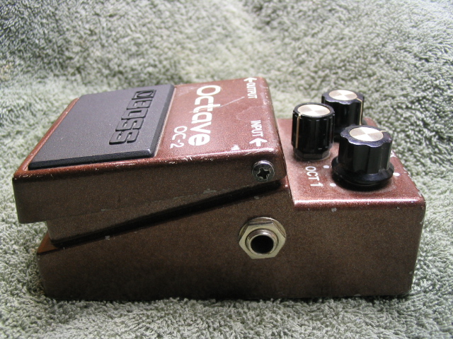
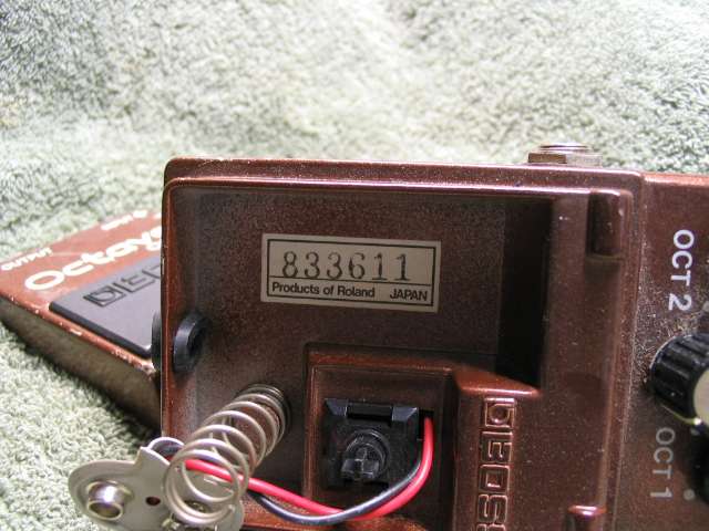
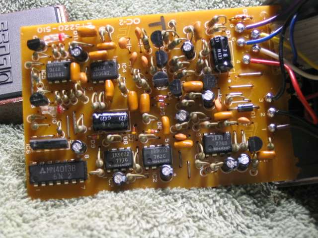
G'day! I have an ACA MIJ OC-2 (1987). Can anyone (DeFrag) point me to a schamatic for it?
Thanks, and regards,
Laurie
|
Edited by - Laurie on 03/04/2008 21:10:29 |
|
|
DeFrag
Moderator

USA
3409 Posts |
|
|
ssanyee
Silver Member

Hungary
288 Posts |
Posted - 03/01/2008 : 10:06:46
|
Ups, DeFrag,
The second link you have posted most probably OS-2 instead of OC-2!
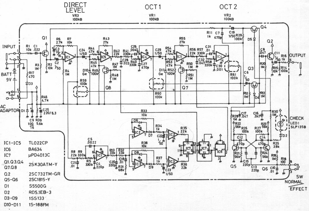
Let me post here the original schematic of OC-2:
cheers  |
Edited by - ssanyee on 03/01/2008 10:08:13 |
 |
|
|
Laurie
Double Platinum Member
Canada
4854 Posts |
Posted - 03/01/2008 : 10:28:52
|
Thanks guys! Righto... I shorted out R17 and D3 to make it PSA compatible. All good so far.
The "fault" that was apparent when I stored this pedal away is quirky. When striking a single note, the tone seems to do this:
- direct sound for about 300ms then
- an abrupt "step" to one of the octave sounds (not sure which one) for a few hundred milliseconds, then
- an abrupt "step" to the other one of the octave sounds (not sure which one) for a few hundred milliseconds, then
- it kinda warbles around (octave sounds turning on and off it seems like)
All the research I've done tells me that it should hold the sound (no warbling) - and the level of the octave components is simply set with the controls.
I will get to work with the 'scope to see what's what, but has anyone seen anything like this before?
Laurie.
|
|
|
|
Dr. Bob
Moderator
Australia
6593 Posts |
Posted - 03/01/2008 : 11:20:59
|
Hi lauries2
They use the 4013 D type Flip Flop as the divide by 1 and divide by 2 divider.
I will admit, that I'd have to go download the datasheet for the BA634
Sounds like it's not getting enough signal into it - hence the skipping or warbling.
Loot at the signal out of the first section of the op-amp
maybe the op-amp of 4013 went a bit south.
Check the coupling caps
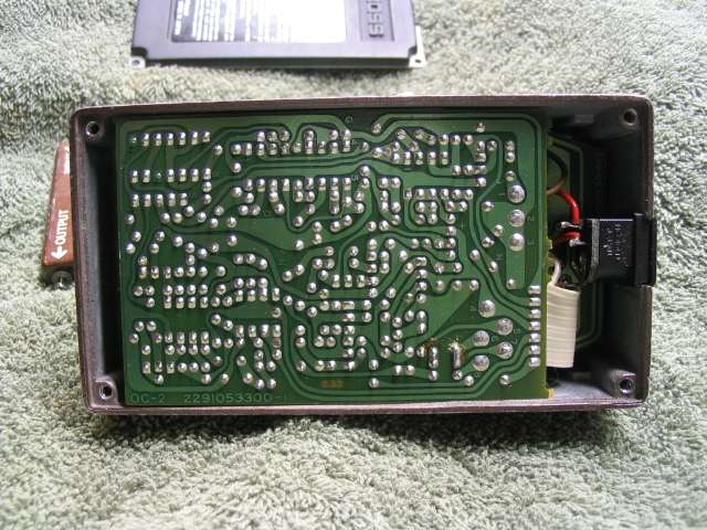
Look for any disturbed components that have have broken off the PCB, or might have come loose,
or wires, or even a crappy dry joint.
I found a spider ball-nest in the CE-2 I repaired 2 nights ago..
If it got over volts, or rev. volts, then I would definitely be looking at the op-amps.
Check the FETS Q7 - Q8
Ssanyee just posted up the Schematic, that should help out heaps.
Good luck, keep us informed of your progress.
Regards Dr. Bob
|
|
|
|
Laurie
Double Platinum Member
Canada
4854 Posts |
Posted - 03/01/2008 : 18:14:36
|
Thank you kindly Dr. Bob.
Visually, all is OK. I'd decided after studying the schematic from ssanyee (many thanks!) that the first thing I should check was the coupling caps... GMTA (or fools seldom differ  ) )
It took a loooong time to find the BA634 data - it's a flip-flop and looks to be the final frequency divider for OCT 2 stage. Not sure though because I only found pin-outs, not a data sheet - it may just be a buffer.
Anyways, I'll spend a couple of hours tracing an injected signal later today and let you know what I find...
Laurie
|
Edited by - Laurie on 03/01/2008 18:20:04 |
|
|
|
DeFrag
Moderator
USA
3409 Posts |
Posted - 03/02/2008 : 00:08:32

|
| Oops, my mistake.. edited out. But which of the two posted OC-2 schems is more accurate, mine or yours? |
|
|
|
Laurie
Double Platinum Member
Canada
4854 Posts |
Posted - 03/02/2008 : 01:10:52
|
ssanyee's circuit is 100% accurate for the pedal I'm working on. Tell me if the rambling I am about to do is isn't something that should be on the forum...
Here is what I think is happening in the circuit:
IC1/IC2/IC3/IC7/IC6 buffer, boost and "square up" the incoming signal then divide the fundamental of the incoming frequency by 2 and by 4.
IC5b (pins 5/6/7) mixes the incoming signal and the 1/2 frequency square wave from the flip-flops. This signal is then fed to IC4b (pins 5/6/7) which is a low pass filter/buffer. IC4b cleans up the signal and feeds it out through VR1 as OCT1.
IC5a (pins 1/2/3) mixes the signal coming out of OCT1 and the 1/4 frequency square wave from the flip-flops. This signal is then fed to IC4a (pins 1/2/3) which is a low pass filter/buffer. IC4a cleans up the signal and feeds it out through VR2 as OCT2.
The fault-finding so far...
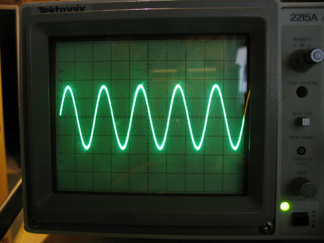
1kHz sine wave test tone injected, all pots turned to maximum:
- Solid 1kHz sine wave signal on IC1 pin 1
- clean crisp 500Hz square wave (9V p-p) coming out of IC7 pin 2
- clean crisp 250Hz square wave (9V p-p) coming out of IC6 pin 2 - the BA634 is something with logic in it (presuming a flip-flop) set to divide by 2
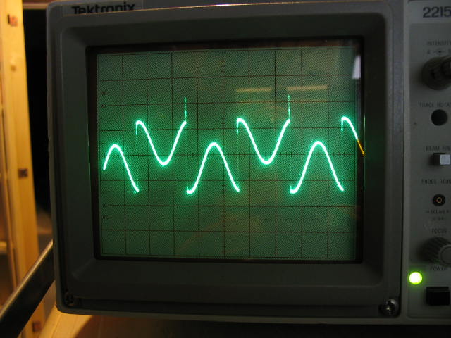
- choppy, nasty mixed 1kHz/500Hz signal from IC5 pin 7 (see pic)
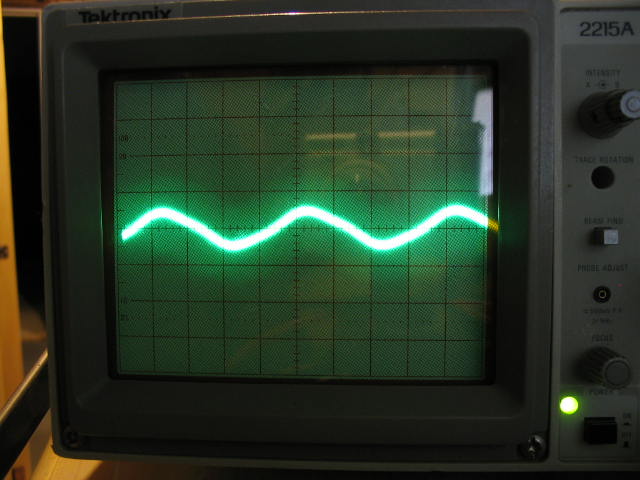
- very low amplitude (70mV p-p) 500Hz signal from IC4 pin 7
- nothing out of IC5 pin 1 or IC4 pin 1
Looks to me like the problem is probably IC5?
Laurie
IC1 pin 1 (2V/division)
IC5 pin 7 (200mV/division)
IC4 pin 7 (50mV/division)
|
|
|
|
Dr. Bob
Moderator
Australia
6593 Posts |
Posted - 03/02/2008 : 02:34:45
|
Hi lauries2
Did you check the SIGNAL on & after the FETS.
But then again certain natches of TL022's, from that era, were not really all that reliable.
Nice CRO - I have the 2213 & Kenwood CS-2150, That I really need the service manual/s for, as it has a fault in the power supply.
Watch the signal levels into the pedal, they are really only looking for a few 100mV.
IF you PM me, I'll send you the actual service sheet (pdf).
it has the BA chip data on it.
I also have another OC-2 Schematic, that was redrawn by someone else.
But I have to studied that one.
Regards Dr. Bob |
|
|
|
Laurie
Double Platinum Member
Canada
4854 Posts |
Posted - 03/02/2008 : 02:43:28
|
quote:
Originally posted by Dr. Bob
Hi lauries2
Did you check the SIGNAL on & after the FETS.
But then again certain natches of TL022's, from that era, were not really all that reliable.
THANK YOU!! for spending the ime to take a look at this!
Q6 and Q7 both have signal on the gates. Q6 has signal after (IC5 pin 5), Q7 (IC5 pin 3) does not. Not sure if that's because the FET is toast or a symptom of a failed IC5 (input short). If it was just a failure of OCT2, I'd say it was Q7 dead, but with the "warbling" I'm thinking probably IC5.
I'll be picking up some TL022's (plus sockets) and a couple of FETs on Monday. Any idea what the current replacement part is for the 2SK30 FETs?
Input voltage is about 500-700 mV. IC1a is a x4 amp (if I recall my op amp maths correctly), so it's a bit high I guess.
Regards,
Laurie. |
Edited by - Laurie on 03/02/2008 02:46:50 |
|
|
|
Laurie
Double Platinum Member
Canada
4854 Posts |
|
|
ssanyee
Silver Member
Hungary
288 Posts |
Posted - 03/02/2008 : 08:55:43
|
lauries2, Dr. Bob, DeFrag,
A few comments from my side:
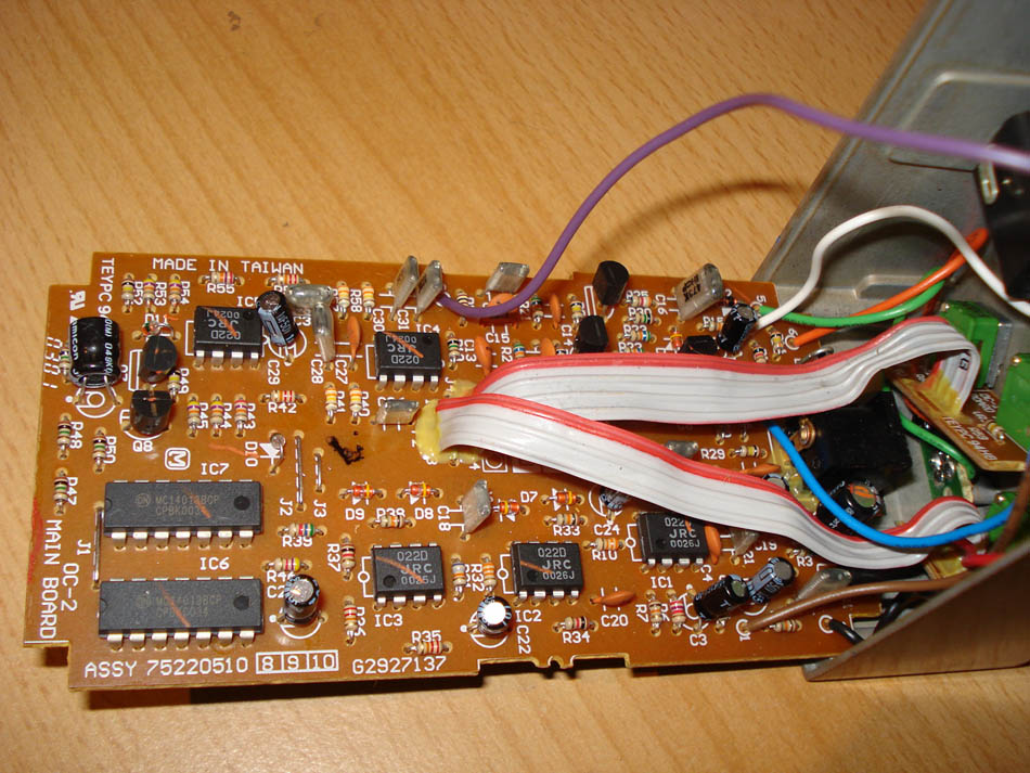
About schematic, I also know well this schem from internet but especially I can not see any 4027 IC in the picture posted by lauries2. Also here is a picture about mine (can not see any4027 too), only difference is that in my OC-2 there is not BA634, obviously half part of IC7 4013 doing this job in this variant (BTW, my OC-2: #JO43342, MIT):
lauries2, nice pictures about scope and logical, consequent problem solving way what you have described above but before you would remove IC5 please check the DC points on the legs (all legs of OPAs should be around half supplied voltage - decided by R46-R39 -, of course, pin 8th always +battery, 4th pin ground). After this confirmation you can step away. Please also check passive parts (resistors, caps), could be some parts crack and it can be a possible reason of problem.
As Dr. Bob has written needed to check the signal on the legs of FETs. The SK30A FET can be replaced by BF245 taking care about legs layout (not same). Because out of Q1 all other FETs are working in swithching mode in this pedal therefore should not be any problem with the replacement!
One more advise: please use -20dB level input signal (~70-100mVeff) to avoid any unnecessary internal distortions!
Hope I could help!
cheers
|
Edited by - ssanyee on 03/02/2008 08:59:21 |
|
|
|
Laurie
Double Platinum Member
Canada
4854 Posts |
Posted - 03/02/2008 : 17:25:12
|
quote:
Originally posted by ssanyee
please check the DC points on the legs (all legs of OPAs should be around half supplied voltage - decided by R46-R39 -, of course, pin 8th always +battery, 4th pin ground). After this confirmation you can step away. Please also check passive parts (resistors, caps), could be some parts crack and it can be a possible reason of problem.
As Dr. Bob has written needed to check the signal on the legs of FETs.
Hi ssanyee! Thank you for the thoughts!
R46-R39 are giving 5V - seems OK. OP amp inputs and outputs are floating at either 3V or 5V. I thought the 3V might be a problem so I checked IC1 pin 3 and it is floating at 3V as well (and IC1 is working fine).
The problem is very apparent at Q8 and Q7. Symptoms have changed a little from yesterday... IC 5 pin 5 (output of Q8) has a waveform that looks like a mixed square and sine wave. IC 5 pin 3 (output of Q7) has a very clean sharp edged square wave (no sign of a sine wave component). Q7 and Q8 are both switching "something", so are probably OK (I'll buy some spares just in case).
Really just noise out of IC5 pin 5, and nothing out of IC4 pins 7 and 1, and nothing out of IC5 pin 1.
All passive components look OK. More and more to me it seems to be IC5. It will be swapped tomorrow when the parts store is open (Sunday here right now) and I'll let you know!
Regards, and thanks!
Laurie
|
|
|
|
ssanyee
Silver Member
Hungary
288 Posts |
Posted - 03/02/2008 : 17:46:54
|
Hi Laurie,
OK, understand, I am intersted in about IC5. If you will change it and if you have any opportunity please check it in other place, in other circuit as a crosscheck confirmation.
However, please update me in case of any result/request!
Wished success!
cheers |
|
|
|
Laurie
Double Platinum Member
Canada
4854 Posts |
Posted - 03/04/2008 : 03:44:41
|
Howdy campers! I hate faultfinding...
The story today:
- changed IC5 - no change
- changed IC4 - no change
- changed Q7 - it got worse (an NTE458 should be OK here? - seemed to not be working at all)
- changed Q7 back to original component and both octave sounds reappeared...
- resoldered D11 (next to Q7) and that fixed the missing octave 2 problem. Must have been a dodgy joint that was disturbed when I was faultfinding on the weekend.
Anyway, now I'm back to the old problem... "warbling".
Let's say a note on the guitar has fundamental frequency = f.
What is happening, exactly, is that the output of the flip-flop (IC7 pin 2) is alternating between f/2 and f, giving the warble - one instant OC1 and OC2 are f/2 and f/4, then next they are f and f/2, then back again. So it seems the circuit is having trouble discriminating between f and the first harmonic, even though the note is plucked cleanly and looks as I would expect coming out of the guitar.
IC1, IC2 and IC3 all seem to be amplifying properly. IC3 pin 7 and IC2 pin 7 are the inverse of each other. So are IC3 pin 1 and IC2 pin 1. Signals into pins 10 and 8 of IC7 are strong, but you can see an f to 2f alternation effect there as well, so IC7 and IC6 are doing what they should with what is given to them.
So the problem appears to be between IC1 pin 7 and IC7 pins 10&8.
Question: is this pedal simply this flakey? Are they all like this?
Anyone have any thoughts where to next?
Regards,
Laurie. |
|
|
|
Laurie
Double Platinum Member
Canada
4854 Posts |
Posted - 03/04/2008 : 08:32:31
|
Just checked the 3dB point for the filter made by IC1b (pins 5,6,7) and it's about 900Hz. Seems good to me? Should be limiting the harmonic content?
I'm stumped. Any help greatly appreciated!!
Regards,
Laurie. |
|
|
|
Topic |
|