| Author |
 Topic Topic  |
|
drasp
Copper Member
USA
17 Posts |
 Posted - 05/31/2008 : 16:37:38 Posted - 05/31/2008 : 16:37:38


|
First post, this is a great forum!
I'm trying to troubleshoot & fix a DD-3 for a buddy from another forum & though I can see some obvious stuff, the testing, etc. is a bit beyond me. I've built pedals & done lots of simple fixes (switches, bad solder joints, replacing obviously bad components, etc.) Need help with how to proceed on this pedal. The issues are:
1) Passes a very low level signal, no delay, no LED, switch tests good
2) 9V gets HOT quickly
3) D6 is dark & PCB is scorched around it, no lifted traces though
4) C46 & C47 looked "bubbled" a bit - damaged? (see picture)
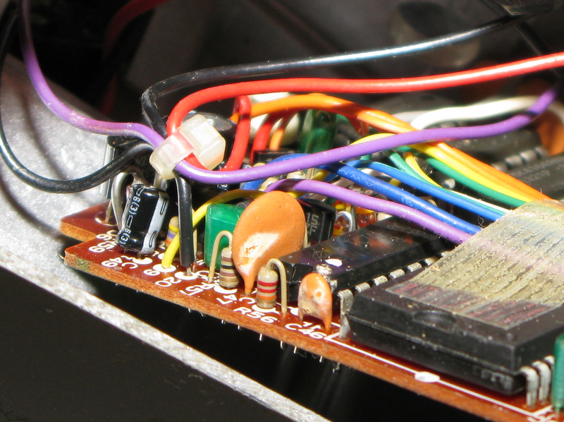
I'm happy to probe for values or snap more pix as need. Of course ANY help would be greatly appreciated!
Thanks!!! |
|
|
Dr. Bob
Moderator

Australia
6593 Posts |
Posted - 05/31/2008 : 17:43:34

|
Hi drasp
First of all welcome to the forum from Australia.
Now it sounds like the DD-3 had a burst of reversed voltage applied to it.
D6 will most likely be shorted out, especially as you mention that the 9V battery gets very hot, it's most likely trying to run into a dead shorted diode.
This is also flattening your battery, so use a known good one for testing.
Check & replace D6.
Sometimes it takes out IC10 the 78L05 100mA mini +5V, voltage regulator as well.
But I would remove D6 & check the DD-3 without D6 installed.
But don't run it off a plug pack adapter, Unless you are 100% sure it's the correct polarity, as this stage.
If it runs, you are in good luck, & just need to replace D6. it's an 11VDV 1W ZENER diode, & it's used for reverse voltage protection.
If you need a Schematic?
Try here, look for the DD-2 it's almost the same, & will get you by.
http://www.freeinfosociety.com/electronics/schempage.php?cat=1
Also check:
C51 C49
And did it get a blast of Rev. volts, or over volts, or both?
Good luck, & tell us how you went.
Maybe Laurie & Christ will chime in on this one as well.
And I hope you stick around a bit, & tell us about your Pedal addiction...
Regards Dr. Bob
|
Edited by - Dr. Bob on 05/31/2008 17:46:29 |
 |
|
|
drasp
Copper Member
USA
17 Posts |
Posted - 05/31/2008 : 19:07:28
|
Thanks Dr. Bob!!! :D
I'll remove D6 this afternoon & report back. No idea what happened to the pedal. Someone over at ShortScale.org was asking for someone to look at a few broken pedals and I offered my limited skills. Hopefully won't be too bad to sort out for him. I'm trying to get more into the diagnostic/design/troubleshooting end of things rather than just fixing simple stuff and doing light mods, etc. Good hobby stuff. ;) |
|
|
|
drasp
Copper Member
USA
17 Posts |
Posted - 05/31/2008 : 19:11:01
|
quote:
Originally posted by Dr. Bob
D6 will most likely be shorted out, especially as you mention that the 9V battery gets very hot, it's most likely trying to run into a dead shorted diode.
This is also flattening your battery, so use a known good one for testing.
Good call - I forgot that when I was testing I used a brank-new Duracell and after only a minute or so it was down to just over 8v! |
|
|
|
Laurie
Double Platinum Member

Canada
4854 Posts |
Posted - 05/31/2008 : 19:39:30
|
quote:
Originally posted by Dr. Bob
Maybe Laurie & Christ will chime in on this one as well.
Welcome drasp!!
I think Dr. Bob is right on the money. Sounds to me like you may be really lucky - if D6 is still short, everything else *should* have been protected. Good luck, and let us know how it goes!
|
|
|
|
drasp
Copper Member
USA
17 Posts |
Posted - 05/31/2008 : 23:49:54
|
| Well, that was nice 'n' simple. Pedal appears to be working 100% now. Just need to dig up the correct diode. Thanks a TON for the help folks - I especially appreciated the linkage to the diagram for the DD-2. I didn't pay very close attention when pulling it apart & it was nice to take a quick look for where the input & output jacks go. |
|
|
|
Dr. Bob
Moderator
Australia
6593 Posts |
Posted - 06/01/2008 : 03:06:17
|
quote:
Originally posted by drasp
Well, that was nice 'n' simple. Pedal appears to be working 100% now. Just need to dig up the correct diode. Thanks a TON for the help folks - I especially appreciated the linkage to the diagram for the DD-2. I didn't pay very close attention when pulling it apart & it was nice to take a quick look for where the input & output jacks go.
Hi drasp
Good to hear all is now well...
BTW that DD-2 Sch. is also for the earlier DD-3 with the 60 pin large IC.
Look carefully at the text on it & you will that both are mentioned.
There have been about 2 or 3 different versions of the DD-3.
The later ones use a large square SMD LSI IC.
If you go over to stinkfoot's site, he has a few pics & a very good explanation, of the different version.
Please take some internal pics, before you put it all back together.
Regards Dr. Bob |
|
|
|
drasp
Copper Member
USA
17 Posts |
Posted - 06/01/2008 : 16:12:08
|
No problem - I'll snap a few full shots when I've got it apart to put in the new diode.
It's deff. a v1.0 dd-3. It's got the off-board mounted DC jack, all through mount comps, the blue MIJ label & the huge IC running the full width of the main board.
I checked out the link in forumite Stinkfoot's profile - http://www.stinkfoot.se/english/index.htm - didn't see anything about the DD-2/3 there except his treble roll off mod. |
Edited by - drasp on 06/01/2008 16:17:14 |
|
|
|
Laurie
Double Platinum Member
Canada
4854 Posts |
Posted - 06/01/2008 : 16:31:29
|
quote:
Originally posted by drasp
No problem - I'll snap a few full shots when I've got it apart to put in the new diode.
It's deff. a v1.0 dd-3. It's got the off-board mounted DC jack, all through mount comps, the blue MIJ label & the huge IC running the full width of the main board.
I checked out the link in forumite Stinkfoot's profile - http://www.stinkfoot.se/english/index.htm - didn't see anything about the DD-2/3 there except his treble roll off mod.
Late model DD-2 = early model DD-3
Rumour has it that that when the cost of RAM plummeted, Boss didn't want to sell the same pedal (DD-2) for a LOT less than they had been selling it, so they rebadged it.
|
|
|
|
stinkfoot
Silver Member

Sweden
181 Posts |
|
|
Dr. Bob
Moderator
Australia
6593 Posts |
Posted - 06/01/2008 : 17:16:01
|
Hi drasp
You didn't look hard enough.
I would have posted the link last night but is was really late, & I was starting to slow down.
BTW:
Stinkfoot comes over here for a visit now & then, of say hi to him on his site.
http://www.stinkfoot.se/andreas/diy/articles/DD3.htm
And thanks to Andreas (Stinkfoot) for allowing us to link to his page.
Regards Dr. Bob
|
|
|
|
drasp
Copper Member
USA
17 Posts |
Posted - 06/01/2008 : 21:26:15
|
Ah-HAH! It was under DIY on ther personal site. Great page!
Yeah, this one is an early v1.0 as I'd thought. Even has the paper serial # under the battery. |
|
|
|
drasp
Copper Member
USA
17 Posts |
Posted - 06/04/2008 : 13:30:49
|
| I have no idea if you can sub a 12v diode for an 11v diode, but Radio Shack has a 12v 1W zener diode - any chance that'd work? Otherwise it's placing ANOTHER order with Mouser/Digi-key, etc. for a $0.08 part. :D |
|
|
|
Laurie
Double Platinum Member
Canada
4854 Posts |
Posted - 06/04/2008 : 14:21:55
|
quote:
Originally posted by drasp
I have no idea if you can sub a 12v diode for an 11v diode, but Radio Shack has a 12v 1W zener diode - any chance that'd work? Otherwise it's placing ANOTHER order with Mouser/Digi-key, etc. for a $0.08 part. :D
No iron-clad guarantee that it will be OK in every conceivable situation, but yes - my standard sub for the 11V zener is the 12V zener. (11V is so hard to find)
What it does is allow 12V maximum to be applied ot the circuit rather than 11V maximum when an incorrect supply is used. Opamps are fine with that, and if you have a pedal with a 78L05 supplying digital chips, the 78L05 will almost certainly be OK. I'd do it without hesitation to one of my pedals.
|
|
|
|
Dr. Bob
Moderator
Australia
6593 Posts |
Posted - 06/04/2008 : 15:47:19
|
Hi drasp & Guys
If you have a few 12V zeners, you could always make up a simple resistor & zener test jig.
measure them all, & find the one with the lowest Knee.
If you only have the one, as Laurie said, use it it's better than no protection.
Zeners in series are cumulative, eg. two series 5.5V zeners would be about 11 volts.
But also remember, that the tolerances are also cumulative.
And I'm not sure if 2 zeners in series, would be as an effective protection method.
They use zeners is there, to basically fail in a SHORTED mode, to protect the rest of the circuit, as your one did.
If it was just a simple 1N400x diode, these usually fail open circuit, & then the rev. voltage goes on to do even more damage.
Remember:
Dr. Bob's Theorem Number 2506, Op-Amps HATE Reversed VOLTAGES...
----
Simple answer, Yes use the 12V Zener...
Regards Dr. Bob |
|
|
|
drasp
Copper Member
USA
17 Posts |
Posted - 06/05/2008 : 03:10:17
|
You guys are awesome! Thanks again for the help. 
Only bummer in this whole equation is that I wasn't able to twist the owners arm & get him to sell me the pedal (I've kind of fallen for it!) |
|
|
|
Topic |
|