| Author |
 Topic Topic  |
|
Dr. Bob
Moderator

Australia
6593 Posts |
 Posted - 08/19/2008 : 16:46:04 Posted - 08/19/2008 : 16:46:04


|
Hi tony, Laurie & Guys
I will print off the Sch. tomorrow at work A3 size & have a bit of a think about it.
I need a hard copy of the sch. it easier that trying to navigate all over a PDF or bitmap of one onscreen.
But for now, would be proceeding along the lines of, looking/testing at the circuit backwards from OUTPUT, back to where the problem seems to be occurring.
Recap for me, was this pedal have Over-Volts or Reverse-Volts applied to it.
it at any chance it was Re.Volts, you can pretty much kiss any op-amps goodbye, or at least consider them to be suspect.
I would also be doing a detailed visual check, using a magnifier, as we saw with (fireman's) recent fix on his Ibanez FL9, in another post, it was crappy solder joints.
Was this pedal new in box, or was it pre-loved?
Do you know if it was every working?
Do you have anything else, you remember might have happened to it, no matter how trivial?
Any chance of some closeup pictures of your DD-2?
Apologies if some of these points have been covered in earlier posts.
Regards Dr. Bob
|
Edited by - Dr. Bob on 08/19/2008 16:49:31 |
 |
|
|
tony
Bronze Member

United Kingdom
142 Posts |
Posted - 08/19/2008 : 17:35:19
|
I can't for the life of me figure out how to post pictures onto this forum. If I try to insert an image, it uploads, but just doesn't appear in the post. Don't know what I'm doing wrong...
Pedal worked fine when I got it, for about a week. Before this it had been virtually unused since new. I have no reason to disbelieve the seller as it looks and feels new. No over or reverse volts (from me, anyway). All solder joints are flawless, including my own.
The only thing I can think of that happened was, just before it broke, I had it hooked up in stereo to a reverb with everything maxed and it went into a mad, screeching out of control feedback. I don't know if that was immediately before it developed the fault, but defintely before and very close in point of time. I actually don't think I used it much that night afterwards and went back to my DM 2. The following day I first noticed the problem.
We've isolated the problem to the expandor side of the NE570. Basically, the signal goes in good and strong and comes out barely audible - except it definitely isn't the chip now, as it's been replaced with a known good NOS part. In addition, all voltages around the chip pins are perfect. In an earlier post I described how, with th epedal hooked up to a guitar and with the controls maxed out, you can hit the strings, wait 800 milliseconds and sure enough the input jumps to healthy line level, then drops exactly with the decay of the strings. As it's an expander the rectifier is vital in the NE570 so my next step is to replace the C33 tantalum rectifier cap with a more modern miniaturised metal film version when it arrives. |
Edited by - tony on 08/19/2008 18:32:36 |
|
|
|
tony
Bronze Member
United Kingdom
142 Posts |
Posted - 08/19/2008 : 17:36:59
|
quote:
Originally posted by starr36
i am flabberghasted.
when this is done, we can talk about my DD-2 that 'can't tell you've turned the feeback knob down"
no, really, we should be taking a collection for starbucks gift cards for something....
fascinating read.
Welcome to our thread. The plot thickens!!
Interesting problem, that. The exact opposite of what I'm experiencing. Have you done all/any of the checks on this thread so far? |
|
|
|
Dr. Bob
Moderator
Australia
6593 Posts |
Posted - 08/19/2008 : 18:02:27
|
quote:
Originally posted by tony
I can't for the life of me figure out how to post pictures onto this forum. If I try to insert an image forum, it uploads, but just doesn't appear in the post. Don't know what I'm doing wrong...
Pedal worked fine when I got it, for about a week. Before this it had been virtually unused since new. I have no reason to disbelieve the seller as it looks and feels new. No over or reverse volts (from me, anyway). All solder joints are flawless, including my own.
The only thing I can think of that happened was, just before it broke, I had it hooked up in stereo to a reverb with everything maxed and it went into a mad, screeching out of control feedback. I don't know if that was immediately before it developed the fault, but defintely before and very close in point of time. I actually don't think I used it much that night afterwards and went back to my DM 2. The following day I first noticed the problem.
We've isolated the problem to the expandor side of the NE570. Basically, the signal goes in good and strong and comes out barely audible - except it definitely isn't the chip now, as it's been replaced with a known good NOS part. As it's an expander the rectifier is vital in the NE570 so my next step is to replace the C33 tantalum rectifier cap with a more modern miniaturised metal film version when it arrives.
Hi tony
Add this line of HTML, where you want the picture to appear, in your post.
I had to post this as a pic, because the Forum tries to execute the HTML code, & you see nothing.

Before you click on the (Post New Reply) button.
Just remember to change the filename.jpg, it also accepts .gif, upper & lower case.
This only works if you have uploaded the pics to Bossarea.
If you can't get it to work, (PM) mail me the Pics, & I will add them to one of your posts.
Better still just post or PM me the list (file names) of the pics you have already uploaded.
They should be in your uploads area, But only the Admin can see them.
---
As far as the tantalum cap goes, replacing it might be a good idea.
I have had these go short circuit n me a number of times. Do you have any other caps there to experiment with, or parallel up a few caps to get cose to the value you need,
until the mini replacement on comes.
Did you order a LOW ESR electro. cap?
or at least a LL Low Leakage type, although most new
brand named caps are LL these days.
Do you have access to an ESR meter, I have been trying to convince Laurie to get one,
it's amazing the faulty electro. caps you will spot with this little tool.
I would also track back from the output, & the op-amp.
While you are waiting on the part.
Regards Dr. Bob
3434
|
Edited by - Dr. Bob on 08/19/2008 18:03:41 |
|
|
|
Laurie
Double Platinum Member

Canada
4854 Posts |
Posted - 08/19/2008 : 18:02:33
|
quote:
Originally posted by Dr. Bob
Hi tony, Laurie & Guys
I will print off the Sch. tomorrow at work A3 size & have a bit of a think about it.
I need a hard copy of the sch. it easier that trying to navigate all over a PDF or bitmap of one onscreen.
But for now, would be proceeding along the lines of, looking/testing at the circuit backwards from OUTPUT, back to where the problem seems to be occurring.
Recap for me, was this pedal have Over-Volts or Reverse-Volts applied to it.
it at any chance it was Re.Volts, you can pretty much kiss any op-amps goodbye, or at least consider them to be suspect.
I would also be doing a detailed visual check, using a magnifier, as we saw with (fireman's) recent fix on his Ibanez FL9, in another post, it was crappy solder joints.
Was this pedal new in box, or was it pre-loved?
Do you know if it was every working?
Do you have anything else, you remember might have happened to it, no matter how trivial?
Any chance of some closeup pictures of your DD-2?
Apologies if some of these points have been covered in earlier posts.
Regards Dr. Bob
Dr. Bob - many thanks! I am at a standstill with this repair... tony summed it up pretty well - we've traced the missing signal back from the pedal output to the output pin of the NE570. Plus we have traced the signal going into the NE570 and it is strong.
We are awaiting a new C33 (gain control cap on the NE570).
Don't be swayed by what I've written above though... This has to be a case of "tech blindness" and I'm hoping you will see the obvious problem I've missed
|
|
|
|
Laurie
Double Platinum Member
Canada
4854 Posts |
Posted - 08/19/2008 : 18:03:43
|
quote:
Originally posted by Dr. Bob
Do you have access to an ESR meter, I have been trying to convince Laurie to get one,
I'm going to get one!!! It's just not very high on the list...  |
|
|
|
Dr. Bob
Moderator
Australia
6593 Posts |
Posted - 08/19/2008 : 18:15:45
|
quote:
Originally posted by Laurie
quote:
Originally posted by Dr. Bob
Do you have access to an ESR meter, I have been trying to convince Laurie to get one,
I'm going to get one!!! It's just not very high on the list...
Hi Laurie & Guys
The ESR Meter & my Fluke, are the number one tools use daily.
You have no idea of the things you can spot with one of these.
We use the extensively in the workshops & Labs, when I am employed.
I have owned one for many years.
Never looked back spending money on one.
Just remember to get one that was designed by Bob Parker, the Aussie Engineer.
It has been licensed recently, search Google for ESR meter & Bob Parker, there is a new blue cased one, that I was considering as an upgrade.
Keep me informed about the progress on the DD-2.
Good night all, I have to go to work in a few hours.
Regards Dr. Bob
|
|
|
|
tony
Bronze Member
United Kingdom
142 Posts |
Posted - 08/22/2008 : 14:57:11
|
OK, it's a no on the new C33. Had to use the tantalum I ordered just in case as it's such a small spot. Pedal still produces exactly the same problem.
At a complete dead end now. I really can't see where else to go from here.... |
|
|
|
Laurie
Double Platinum Member
Canada
4854 Posts |
Posted - 08/22/2008 : 15:11:56
|
| Hi tony! It really has to be something simnple that we are just blind to. I'll have another good look through the schematic tomorrow (Sat) now we've been away from it for a bit. |
|
|
|
tony
Bronze Member
United Kingdom
142 Posts |
Posted - 08/22/2008 : 15:29:45
|
quote:
Originally posted by Laurie
Hi tony! It really has to be something simnple that we are just blind to. I'll have another good look through the schematic tomorrow (Sat) now we've been away from it for a bit.
Totally. It goes in good, comes out bad. There's nothing on the output at pin 10 to drag it down Except R42 at 47k, R41 at 22K and C20 which is one of those near indestructible green film caps BOSS used to use.
- I think I'm possibly right in saying this all attaches to the inverted input for the output op amp in the NE570. If the NE570 wasn't getting an inverted input it wouldn't output properly? But it must be, because all the compnents test fine (although I can't check C20). |
Edited by - tony on 08/22/2008 17:06:40 |
|
|
|
Laurie
Double Platinum Member
Canada
4854 Posts |
Posted - 08/24/2008 : 07:27:37
|
tony... I'm stumped. The only thing it can be is a faulty NE570. But it cant be a faulty NE570.
Are the tracks behind the NE570 all pristine? no possibility of a hairline fracture or nearby dry joint?
Dang... if you lived nearby I'd invite you over for a beer and put it on the signal generator and scope.
|
|
|
|
Dr. Bob
Moderator
Australia
6593 Posts |
Posted - 08/24/2008 : 07:47:42
|
Hi tony, Laurie & Guys
At this point, Some pictures would be good.
You said you upload some, but can't get them to display.
Please give me a list of the exact filenames.jpg that you have already uploaded, & I will see, if I can get them to display.
Regards Dr. Bob |
|
|
|
Dr. Bob
Moderator
Australia
6593 Posts |
Posted - 08/24/2008 : 08:09:19
|
Hi tony
Ok, thanks a heap of efforts on Bossarea's part,
I can see the files that you have uploaded.
dm2.jpg - 85K
DSC_0550.jpg - 85K
P1030674.jpg - 601K
I'll see what I can get to display, although the last file is over 600K.
The first 2 files are the pic of the really beatup DM-2
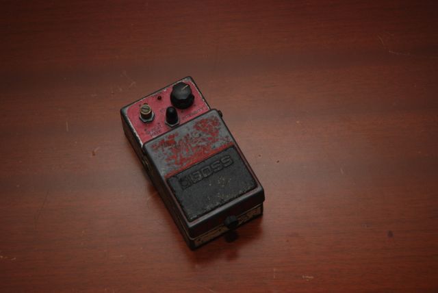
The second pic looks like it was too big for the server upload at 600K & timed out.
PM me your Pics, or just re-size them to around 100-plus-K
Removed corrupted image by request.
Regards Dr. Bob |
Edited by - Dr. Bob on 08/24/2008 16:45:40 |
|
|
|
tony
Bronze Member
United Kingdom
142 Posts |
Posted - 08/24/2008 : 16:34:37
|
Will supply pictures ASAP. They won't really tell you anything, it looks just like the DD2/DD3A image on the stinkfoot site. Seriously, there is nothing amiss with the board at all.
I'm beginning to wonder what points of contact there are between the two channels inside the NE570. I'm not planning on doing it again, but when I accidentally shorted pin 1 to ground across C32 (the old C32 and the old NE570) I got exactly the same out of control feedback I experienced shortly before the pedal originally stopped functioning. Obviously the two channels share the voltage supply, but what other internal points of contact might there be? Might something on the compressor side be dragging down the expandor side?
Given that the problem is really with feedback more than effect level and that I can't be certain exactly what the two channels share inside the NE570, I'm going to apply a bit of "fuzzy logic" and just replace all susceptible components, ie; all electrolytics around it. Particularly C26, C30 and C31.
Hell, if I just keep replacing things, I'll get there eventually!
EDIT: Dr Bob/Bossarea - Could you get rid of that massive image I uploaded because it's stretching the thread out!! |
Edited by - tony on 08/24/2008 16:36:25 |
|
|
|
Laurie
Double Platinum Member
Canada
4854 Posts |
Posted - 08/24/2008 : 16:44:45
|
quote:
Originally posted by tony
I'm beginning to wonder what points of contact there are between the two channels inside the NE570. I'm not planning on doing it again, but when I accidentally shorted pin 1 to ground across C32 (the old C32 and the old NE570) I got exactly the same out of control feedback I experienced shortly before the pedal originally stopped functioning. Obviously the two channels share the voltage supply, but what other internal points of contact might there be? Might something on the compressor side be dragging down the expandor side?
Given that the problem is really with feedback more than effect level and that I can't be certain exactly what the two channels share inside the NE570, I'm going to apply a bit of "fuzzy logic" and just replace all susceptible components, ie; all electrolytics around it. Particularly C26, C30 and C31.
Hell, if I just keep replacing things, I'll get there eventually!
EDIT: Dr Bob/Bossarea - Could you get rid of that massive image I uploaded because it's stretching the thread out!!
The problem is that the compressor side seems to be working (otherwise there would be no signal going in to the expander). So the compressor side is probably OK.
Just for giggles, desolder D5 (disconnect the connection between the NE570 and the reset circuit) and see if that makes a difference. |
|
|
|
Topic |
|
|
|