| Author |
 Topic Topic  |
|
tony
Bronze Member

United Kingdom
142 Posts |
 Posted - 08/24/2008 : 22:31:23 Posted - 08/24/2008 : 22:31:23


|
quote:
The problem is that the compressor side seems to be working (otherwise there would be no signal going in to the expander). So the compressor side is probably OK.
Just for giggles, desolder D5 (disconnect the connection between the NE570 and the reset circuit) and see if that makes a difference.
Yeah, I just think there might be some strange thing happening that we couldn't identify exactly because of the aforementioned lack of knowledge about what/how/where the two channels are connected.
I was thinking about D5, actually. It looks fine, but you never know. I guess if it was short it might ground out the gain via Q12 and the muting circuit? I've tried it for continuity, which was a negative, but still, worth a go. Besides I know that multimeters don't always produce enough current to test diodes properly.
Plus, there isn't anything else connected to the expander side that we haven't already thought of(!)
I have a question, actually. When a diode is represented on a schematic, does the arrow show the direction of travel, or is it opposite? I've read some conflicting things about this. For example, is D5 showing us that the signal goes down (direction of arrow) or up? I suppose up would make make more sense.
Actually, yeah, looking at D4 and D6 it is opposite and therefore up.
I'll give it a go tomorrow - had a couple of beers with dinner so best not do any work on this tonight!! |
Edited by - tony on 08/24/2008 23:07:27 |
 |
|
|
Laurie
Double Platinum Member

Canada
4854 Posts |
Posted - 08/25/2008 : 01:41:23

|
quote:
Originally posted by tony
I have a question, actually. When a diode is represented on a schematic, does the arrow show the direction of travel, or is it opposite? I've read some conflicting things about this. For example, is D5 showing us that the signal goes down (direction of arrow) or up? I suppose up would make make more sense.
There are two concepts in electronics - "conventiopnal current", and electron flow.
Back in the day before it was understood that it is the electrons that move, it was assumed that positive charges move. These (now historical and hypothetical) charges are called "conventional current". All electronic device schematics show conventional current. For a diode, if you apply positive voltage to the tail of the arrow and negative voltage to the head, current will flow. Convential current says positive charges are flowing in the direction of the arrow. What is actually happening at the physical level is that electrons are flowing from the negative voltage terminal to the positive voltage terminal (opposite to the direction of the arrow).
|
|
|
|
tony
Bronze Member
United Kingdom
142 Posts |
Posted - 08/25/2008 : 03:03:18
|
Thanks for that, Laurie.
Got impatient and did it. With D6 out of the circuit the problem remains exactly the same.
I've noticed something recently. The signal from pin 7 of the NE570 (compressor out) is actually a bit louder than the delayed signal at R44 and pins 14 &15. Pin 7 is actually quite loud. Pins 14 & 15 are still perfectly clear - just not quite as loud. Don't know if this has any significance. Pin 10 still barely audible in comparison to both. |
Edited by - tony on 08/25/2008 03:38:48 |
|
|
|
Laurie
Double Platinum Member
Canada
4854 Posts |
Posted - 08/25/2008 : 04:33:44
|
The volume levels seem OK to me. The signal from pin 7 goes through a bunch of processing so I'd expect it to be slightly different to the signal on pin 14.
Still stumped here...
|
|
|
|
Laurie
Double Platinum Member
Canada
4854 Posts |
Posted - 08/25/2008 : 04:40:39
|
You know, there is one more thing we can try.
Pull R40 and C29. Use a (say) 10k resister to jumper from the pad of R40 that connects to C34 across to the pad of C29 that connects to R37.
This will take the expander completely out of the circuit. If the pedal works fine (but maybe sounds a bit "muffled" because the expander is missing) then we will have proved the rest of the circuit and confirmed (again) that it's the NE570.
|
|
|
|
tony
Bronze Member
United Kingdom
142 Posts |
Posted - 08/26/2008 : 12:38:57
|
OK, this is interesting. Might be nothing (as far as the problem is concerned) but I can't believe I've just noticed it. Studying the PCB carefully in the overcast gloom of the British summer, I found this.
Never been anywhere near this with the soldering iron. Even if I had, I couldn't do anything that would look like this. The melted looking hole is massive and obvious in the magnified picture but near impossible to see with the naked eye.
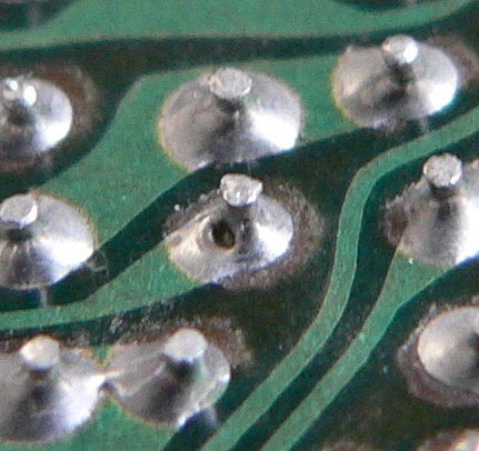
This is the ground side of C30, a 6.3v 47uf electrolytic on the inverted input of the compressor side. Might have got quite hot by the look of it. I've got some nice Sanyo ones of these, so definitely worth replacing. Back at work this week, unfortunately, so will do ASAP and report back. |
Edited by - tony on 08/26/2008 17:03:32 |
|
|
|
Laurie
Double Platinum Member
Canada
4854 Posts |
Posted - 08/26/2008 : 17:03:19
|
Looks worse than it is. Don't think its dry.
|
|
|
|
Dr. Bob
Moderator

Australia
6593 Posts |
|
|
tony
Bronze Member
United Kingdom
142 Posts |
Posted - 08/29/2008 : 15:33:10
|
quote:
Originally posted by Laurie
You know, there is one more thing we can try.
Pull R40 and C29. Use a (say) 10k resister to jumper from the pad of R40 that connects to C34 across to the pad of C29 that connects to R37.
This will take the expander completely out of the circuit. If the pedal works fine (but maybe sounds a bit "muffled" because the expander is missing) then we will have proved the rest of the circuit and confirmed (again) that it's the NE570.
Right, finally got round to doing this. With the expandor totally out of the circuit, the pedal works fine. A bit hissy and weird, with the regeneration maybe not totally up to standard, but substantially fine. I just can't believe it's the chip again. Unless it turns out this is some kind of common failure mode for NE570's. |
Edited by - tony on 08/29/2008 15:47:20 |
|
|
|
Laurie
Double Platinum Member
Canada
4854 Posts |
Posted - 08/29/2008 : 15:42:09
|
Cool! Well, we know where it is for sure.
I've never seen an NE570 fail... so it's almost got to be somethijng around the chip that we just can't see because it's so obvious.
|
|
|
|
tony
Bronze Member
United Kingdom
142 Posts |
Posted - 08/29/2008 : 15:52:58
|
Incidentally, if you look at the schematic, there are two "R40"s - one connected to pins 2 and 3 and one connected to pins 14 and 15. This was momentarily confusing when it came to removing it - it's actually R43!
It's not that 47uf I suspected, although it did look slightly weird when I pulled it, with an almost imperceptible smidge of brown stuff on the bottom. I replaced it with no effect. What about C20? Unlikely, I know. |
Edited by - tony on 08/29/2008 15:53:35 |
|
|
|
Dr. Bob
Moderator
Australia
6593 Posts |
Posted - 08/29/2008 : 16:33:27
|
Hi Tony
I know this will sound like a really dumb question, but are you actually
measuring the values of the resistors around the 570?
Carbon film resistors aren't know for their quality or reliability.
I have also learned not to trust poly caps whatever colour they are:
Green - Clear - Orange.
lift one end of the resistors to disconnect them from any possible circuit loading, & just measure them.
Compare them to the actual colour bands & schematic values.
It's harder to test poly or other caps without the correct equipment, it's just easier to replace them.
I'm glad you & Laurie have narrowed it down to something associated with the the NE570 Compander.
Like Laurie, I have never known one to go faulty.
Any change the electro caps in that area might be inserted incorrectly with the wrong polarity.
It's easy to overlook the most obvious faults.
It would be nice to see some detailed pics of both sides of the area.
Also didn't you write/mention that you slipped with the test probe after installing the 570, might this have caused a possible second failure of the 570?
quote:
Back on page 5 you wrote:
I'm beginning to wonder what points of contact there are between the two channels inside the NE570. I'm not planning on doing it again, but when I accidentally shorted pin 1 to ground across C32 (the old C32 and the old NE570) I got exactly the same out of control feedback I experienced shortly before the pedal originally stopped functioning.
Also remember that Tantalum caps have the Positive lead marked,
Where normal Electro caps have their Negative lead marked.
I hope you don't misunderstand my post as insulting or negative.
Remote diagnostics can be very difficult.
Good luck
Regards Dr. Bob |
Edited by - Dr. Bob on 08/29/2008 16:42:52 |
|
|
|
tony
Bronze Member
United Kingdom
142 Posts |
Posted - 08/29/2008 : 16:38:37
|
quote:
Also didn't you write/mention that you slipped with the test probe after installing the 570, might this have caused a possible second failure of the 570?
Regards Dr. Bob
No, that was only with the first one - all I did was momentarily short out the connection between pin 1 and ground. It didn't do anything at all because the problem remained unchanged. I've been measuring R41 and R42 in circuit where they showed perfect values but I suppose I could pop them out and have a look. I've got replacement bits standing by for everything around the NE570 now!!
All the tantalums, etc are in the right way around. |
Edited by - tony on 08/29/2008 16:44:47 |
|
|
|
Dr. Bob
Moderator
Australia
6593 Posts |
Posted - 08/29/2008 : 16:49:35
|
Hi tony
You only have to lift one of the component legs to measure it,
just as long as it's disconnect from the circuit.
Gently move the poly caps in that area to see if one seems to have a loose solder joint.
I have seen solder joints that look perfect, but the lead is loos & disconnected in inside the joint.
This happens a lot in Sh!tty PC Switching power suppliers.
Also look for a leg that may be broken off a cap, but appears to be ok.
And as Laurie already mentioned, look for hair line cracks in the PCB.
Regards Dr. Bob
|
|
|
|
tony
Bronze Member
United Kingdom
142 Posts |
Posted - 08/29/2008 : 17:13:36
|
quote:
Originally posted by Dr. Bob
Hi tony
You only have to lift one of the component legs to measure it,
just as long as it's disconnect from the circuit.
Because of how they're all inserted (upright) and the unbelievably cramped nature of the board, it's easier to just take them out. If ever there was a case to be made for surface mount, the DD 2 makes it.
Will definitely give C20 a very gentle waggle.
This thread will soon be moving into it's (hopefully) lucky seventh page.
EDIT: No wobble on C20. Not that that's definitive. Got some pics now, as soon as my battery charges up I'll upload them. |
Edited by - tony on 08/29/2008 17:23:27 |
|
|
|
Topic |
|
