| Author |
 Topic Topic  |
|
Kurt
Copper Member
8 Posts |
 Posted - 08/01/2008 : 03:53:43 Posted - 08/01/2008 : 03:53:43


|
Hi guys, I found this site as I was surfing for info on my dead DM-2. I've had it since the mid-80's and she has worked fine until recently. A few months ago it began only working hit-or-miss (either working fine, normal as ever, OR not at all) and now nothing. Doesn't pass a signal, no LED, nothing at all. I've attached a few pics for what it's worth. Using a 9v battery as power. It worked fine WHEN it worked, even when it was intermittent, so I'm thinking it could be a power issue, or the switch? I am not afraid to do some trouble-shooting with a solder gun if you can point in a likely direction. Heck, it already doesn't work, can't make it any worse!
Thanks in advance for any tips.
Image display code added by moderator
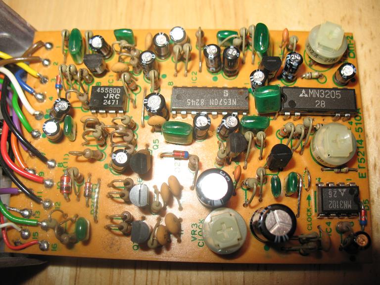
Download Attachment:  DM2_board1.JPG 101.69�KB DM2_board1.JPG 101.69�KB

Download Attachment: DM2_board2.JPG 96.32�KB
 |
Edited by - Dr. Bob on 08/04/2008 09:54:26 |
|
|
ChristoMephisto
Platinum Member

Canada
1288 Posts |
|
|
Kurt
Copper Member
8 Posts |
Posted - 08/02/2008 : 03:13:06
|
| Hey man thanks for the reply, and the links. I'll take a look at the schematics and my pedal and get back to you. Yes, I have a multimeter but will admit that I don't know what "checking comps" means. |
 |
|
|
ChristoMephisto
Platinum Member
Canada
1288 Posts |
Posted - 08/02/2008 : 04:37:21
|
Just means check the components, see if they measure up correct to their values.
Also continuity or the 'beep-test', and the pots
Check the solder joints on the jacks, they may have broken |
|
|
|
andrewb
Copper Member
Australia
19 Posts |
Posted - 08/02/2008 : 20:41:29


|
hey kurt
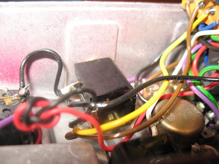
in your 2nd pic, bottom right of the curcuit board, there is a grey wire.... it has a red, white and bare wire in it...
could you please tell me where the bare wire goes?
mine was just sitting in there... and im not sure what it is meant to do.
thanks in advance  |
|
|
|
Kurt
Copper Member
8 Posts |
Posted - 08/03/2008 : 03:40:51
|
| No problem Andrew, will check it out and get back to you tomorrow (Sunday). |
|
|
|
andrewb
Copper Member
Australia
19 Posts |
Posted - 08/03/2008 : 11:08:26
|
| thanks :) |
|
|
|
Laurie
Double Platinum Member

Canada
4854 Posts |
Posted - 08/03/2008 : 14:55:04
|
quote:
Originally posted by Kurt
Hi guys, I found this site as I was surfing for info on my dead DM-2. I've had it since the mid-80's and she has worked fine until recently. A few months ago it began only working hit-or-miss (either working fine, normal as ever, OR not at all) and now nothing. Doesn't pass a signal, no LED, nothing at all. I've attached a few pics for what it's worth. Using a 9v battery as power. It worked fine WHEN it worked, even when it was intermittent, so I'm thinking it could be a power issue, or the switch? I am not afraid to do some trouble-shooting with a solder gun if you can point in a likely direction. Heck, it already doesn't work, can't make it any worse!
Thanks in advance for any tips.
Hi Kurt! Welcome!!
So, your DM-2 looks OK on quick visual inspection. Actually, it looks like it is in pristine condition
Just want to clarify a couple of things:
1) When it was intermittent, was it like it is now? "Doesn't pass a signal, no LED, nothing at all"
2) Are you ONLY using a 9V battery as power? Were you ONLY using a 9V battery as power when it was intermittent?
3) What condition is the input jack in? Can you post pics of the wiring (looking into the pedal towards the jacks and back of the switch?
Regards,
Laurie. |
|
|
|
Dr. Bob
Moderator

Australia
6593 Posts |
Posted - 08/03/2008 : 15:19:49
|
Hi Kurt
Welcome to the forum from Australia.
Regards Dr. Bob |
|
|
|
Kurt
Copper Member
8 Posts |
Posted - 08/04/2008 : 03:26:40
|
Andrew - the bare wire is seen in the lower left of pic #1 - attached to solder point #13 (excuse my rookie lingo).
Laurie - thanks for the welcome! To answer your questions:
1 - Yes, when intermittent, it would either work fine (no problems), or like it is now, i.e not at all: no LED etc., like it isn't getting any juice whatsoever.
2 - yes, ALWAYS and ONLY used 9V batteries.
3 - three pics of input jack attached for your viewing pleasure.
Dr. Bob - thank you too for the welcome. Man this place is great!
Image display code added by moderator
Download Attachment: jack1.JPG 76.2�KB
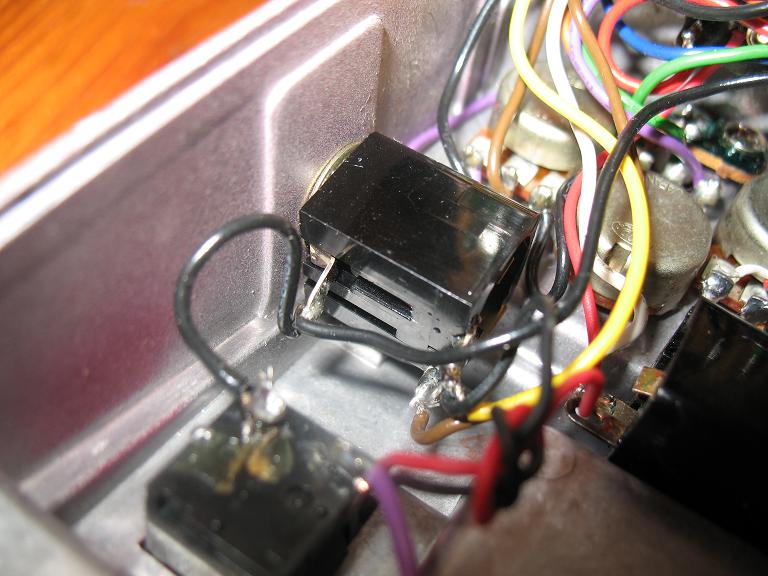
Download Attachment: jack2.JPG 72.45�KB
Download Attachment: jack3.JPG 67.56�KB

|
Edited by - Dr. Bob on 08/04/2008 09:13:08 |
|
|
|
Laurie
Double Platinum Member
Canada
4854 Posts |
Posted - 08/04/2008 : 04:14:54
|
Well, well, well...
The lug on the input jack with the yellow and black wires looks dodgy. Those frayed strands should not be there. Check that the yellow wire is connected to terminal 3 on the board... assuming this is the case, a fault on that lug of the input jack will cause exactly the symptoms you are experiencing.
Reterminate (cut and strip if necessary, and resolder) the yellow wire and black wire on that lug and you may find the problem is fixed. If not, those frayed strands need to be fixed anyway |
Edited by - Laurie on 08/04/2008 04:16:28 |
|
|
|
andrewb
Copper Member
Australia
19 Posts |
Posted - 08/04/2008 : 09:35:42
|
hey kurt
i know that its attatched to #13 on the curcuit board... but where is the other end of the wire attatched to?
hehe :) |
|
|
|
Laurie
Double Platinum Member
Canada
4854 Posts |
Posted - 08/05/2008 : 02:53:21
|
quote:
Originally posted by andrewb
hey kurt
i know that its attatched to #13 on the curcuit board... but where is the other end of the wire attatched to?
hehe :)
It's not attached to anything... it is a "single ended shield". It attaches to pin 13 then runs up the wires from pins 15 and 16 until it nearly (but not quite) reaches the pot lugs. Don't attach the "pot end" to anything - that would cause hum. |
|
|
|
Kurt
Copper Member
8 Posts |
Posted - 08/05/2008 : 03:44:18
|
Laurie - I re-soldered the black and yellow wires onto the lug but no dice. Good thought though! Is there a way to check to see if the switch is good? The input jack? Any quick checks I could do with a multi-meter? Thanks as always.
|
|
|
|
Laurie
Double Platinum Member
Canada
4854 Posts |
Posted - 08/05/2008 : 05:50:57
|
The switch won't be faulty - it would simply not change ON/OFF if the switch was bad. To get a completely dead pedal, it has to be a power failure somewhere.
I'll think on it some more overnight/ |
|
|
|
andrewb
Copper Member
Australia
19 Posts |
Posted - 08/05/2008 : 19:47:39
|
quote:
Originally posted by Laurie
quote:
Originally posted by andrewb
hey kurt
i know that its attatched to #13 on the curcuit board... but where is the other end of the wire attatched to?
hehe :)
It's not attached to anything... it is a "single ended shield". It attaches to pin 13 then runs up the wires from pins 15 and 16 until it nearly (but not quite) reaches the pot lugs. Don't attach the "pot end" to anything - that would cause hum.
ahhh fair enough
i will clip the end off it so it doesnt go touching anything....
i am guessing i have a faulty switch then....
hey kurt... have you checked your plugs? :) |
|
|
|
Topic |
|
 DM2_board1.JPG
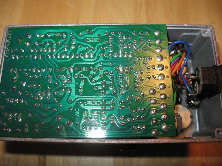 DM2_board2.JPG
 jack1.JPG
 jack2.JPG
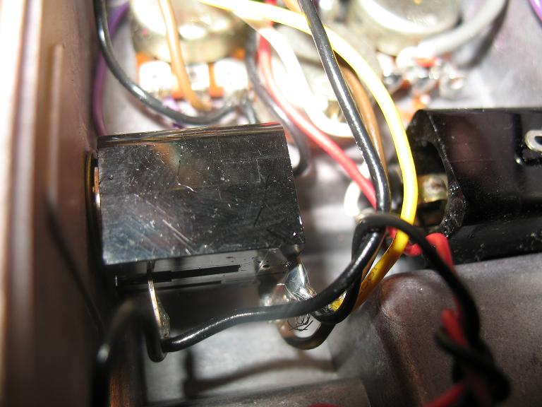 jack3.JPG