| Author |
 Topic Topic  |
|
Mesjoggah
Gold Member

Netherlands
595 Posts |
 Posted - 01/09/2009 : 19:09:43 Posted - 01/09/2009 : 19:09:43


|
quote:
Originally posted by Laurie
These are the things that don't fit together in my mind:
1) Set your meter to ohms and measure from the middle leg of Q14 to the pedal case - what resistance do you get? (it should be infinite - an "open circuit") 0,6(on a 20k scale)
This tells us that there is a connection from the collector of Q14 to ground. There should not be one - mine reads infinite.
2a) Pull Q14 out of the board and measure the resistance between the two legs that were closest to the edge of the board. Should be infinite Ohms (open circuit). there's no reading
2b) With Q14 out of the board, measure from the solder pad for the middle leg of Q14 to ground (the pedal case). Should be infinite Ohms (open circuit). there's no reading
In point #1 above, there is a reading to ground. With Q14 pulled, that reading should occur either inside Q14 (it does not - point #2a) or in the circuit on the board (it does not - point #2b).
OK. Let's check this - with the pedal powered up, is there 9V between the pedal case and the side of R46 furthest from the edge of the board?
i re-measured 2b and now i had 43ohm resistance..
i have 9 volts on r46 on the side furthest from the edge |
Edited by - Mesjoggah on 01/09/2009 19:21:27 |
 |
|
|
Laurie
Double Platinum Member

Canada
4854 Posts |
Posted - 01/09/2009 : 19:53:16

|
OK... that makes a lot more sense!  The fault is definitely on the board. The fault is definitely on the board.
There is nothing that connects the collector of Q14 to ground - now we know Q14 is OK, there are no other components that could have failed to cause this.
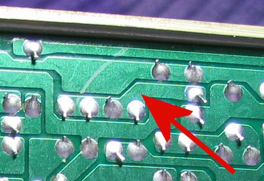
There almost HAS to be a small solder dag or something shorting that track to ground. Alternatively, a previous owner has done something REALLY strange to the board. Can you see anything at all that looks strange around the track that the middle pin of Q14 (the Collector) solders to? This is the track that R45, R46, R48, C31 are also soldered to.
Time for some high-res pics I think?
Alternatively, one-by-one remove the following components and re-do the #2b measurement. If the measurement goes to infinite, I'll be surprised, but let's try it. R45, R46, R48, C31.
|
|
|
|
Mesjoggah
Gold Member
Netherlands
595 Posts |
Posted - 01/10/2009 : 08:26:10
|
I can't figure out were on the board the fault lies, i one by one took out R45, R46, R48, C31, q15, c33, r50 and measured resistance which increased everytime i pulled a component, so the connection to ground must be made somewhere else on the track.
|
|
|
|
Laurie
Double Platinum Member
Canada
4854 Posts |
Posted - 01/10/2009 : 08:46:59
|
High res photos of the area are the next thing if you can? Top and bottom of the board.
With Q14, R45, R46, R48, C31 all pulled, are you still getting a reading to ground from the track? There should be no more components connecting to the track...?
This is the track on mine:
Assuming the components are all pulled and you are still getting a reading to ground, there almost has to be a dag/fault/something along this line:
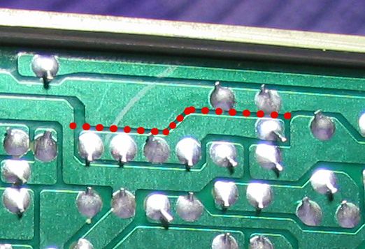
If all this is true, try using a sharp knife and scoring along the gap between the tracks. |
Edited by - Laurie on 01/10/2009 09:01:30 |
|
|
|
Mesjoggah
Gold Member
Netherlands
595 Posts |
Posted - 01/11/2009 : 09:30:27
|
What i meant was: I pulled R45, R46, R48, C31 then measured from the middle leg of q14 - infinite
When measured from the inner solder pad of R48 - 55,1 ohms
When measured from the inner solder pad of C31 - 55,1 ohms
When measured from the inner solder pad of R45 - infinite
When measured from the Inner solder pad of R46 - 05,9 ohms
R48 and C31 are soldered to the same track so they measure the same
With R50 pulled i get infinite when measured from the inner solder pads of R48 and C31.
|
Edited by - Mesjoggah on 01/11/2009 15:16:07 |
|
|
|
Laurie
Double Platinum Member
Canada
4854 Posts |
Posted - 01/11/2009 : 17:36:47
|
I've traced out the circuit for the flip-flop:
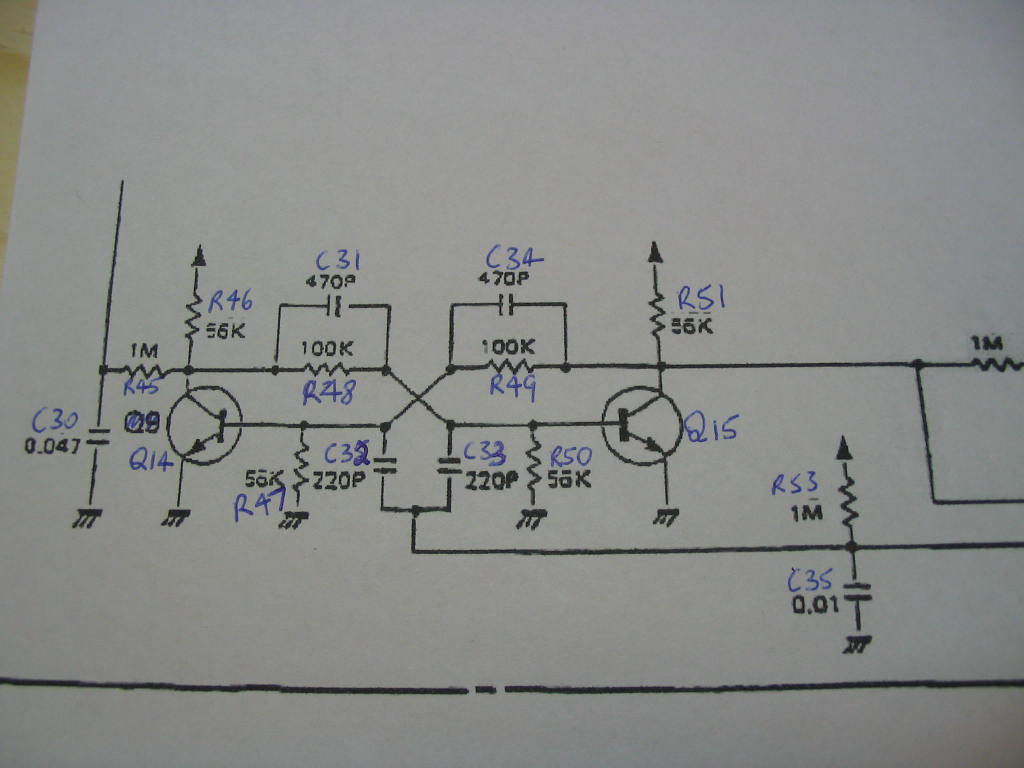
Might your meter be reading "k" Ohms, rather than Ohms? A reading of 55.1 kOhms from the inner solder pad of R48/C31 to ground is exactly right... (that's the path through R50)
If your meter has been reading kOhms all through this, we may have been heading down a blind alley.
If you put all the components back in, make the following measurements:
1) Middle leg of Q14 to pedal case and middle leg of Q15 to pedal case - are they the same?
2) Leg of Q14 furthest from the edge to pedal case and leg of Q15 closest to R47 to pedal case - are they the same?
|
|
|
|
Mesjoggah
Gold Member
Netherlands
595 Posts |
Posted - 01/11/2009 : 19:14:52
|
quote:
Originally posted by Laurie
I've traced out the circuit for the flip-flop:
Might your meter be reading "k" Ohms, rather than Ohms? A reading of 55.1 kOhms from the inner solder pad of R48/C31 to ground is exactly right... (that's the path through R50)
If your meter has been reading kOhms all through this, we may have been heading down a blind alley.
If you put all the components back in, make the following measurements:
1) Middle leg of Q14 to pedal case and middle leg of Q15 to pedal case - are they the same?
2) Leg of Q14 furthest from the edge to pedal case and leg of Q15 closest to R47 to pedal case - are they the same?
Thanks for your patience with me Laurie..
I didn't realise i put my meter on K ohms.. should i best set it on the '200' scale?
1) Middle leg of Q14 to pedal case and middle leg of Q15 to pedal case - are they the same?
Both infinite
2) Leg of Q14 furthest from the edge to pedal case and leg of Q15 closest to R47 to pedal case - are they the same?
Both infinite
|
|
|
|
Laurie
Double Platinum Member
Canada
4854 Posts |
Posted - 01/11/2009 : 20:52:14
|
So I've gone back through all the posts in the thread to try to extract a clearer picture of where we are with this. I've summarised what i think I've found below. Is this your understanding too?
Description of the symptoms:
The led goes on but there's no distortion, knobs do not make any difference to the clean sound except for the level that does seem to affect the sound a bit.
There's absolutely no difference in sound with the check LED on or off.
Clipping diodes do not light up.
It doesn't work with either adapter or battery.
All components look fine at a visual inspection.
Replaced the op-amp for a known good one, but fault it stays the same.
Q14 has been changed for a known good one, but fault stays the same.
I would say the LED is a little less brighter compared to other MIT pedals.
Measurements taken so far:
Measured Q2 (the middle leg), it reads zero volts no matter if it's turned off or on.
Measured both d1 and d4 with the 'check LED' off, both zero volts, then measured both d1 and d4 with the 'check LED' on, both read 3 volts (measured from the stripe end)
Q15 base with LED on = 0,6 volts
Q15 base with LED off = 0 volts
Q14 base with LED on = 0 volts
Q14 base with LED off = 0,6 volts
The middle leg of Q14 (collector) should be changing from 0V to about 5 or 6 volts with the check LED going on and off as you press the switch - 0 volts no matter if the LED is on or not
Both sides of R45 should be changing from 0V to about 5 or 6 volts with the check LED going on and off as you press the switch - the outer side doesn't change and the inner side changes to 3 volts
Measure R46 - 56k
Pull Q14 out of the board and measure the resistance between the two legs that were closest to the edge of the board. Should be infinite Ohms (open circuit) - there's no reading
With Q14 out of the board, measure from the solder pad for the middle leg of Q14 to ground (the pedal case). Should be infinite Ohms (open circuit) - there's no reading
There is 9 volts on r46 on the side furthest from the edge
Middle leg of Q14 to pedal case and middle leg of Q15 to pedal case - Both infinite
Leg of Q14 furthest from the edge to pedal case and leg of Q15 closest to R47 to pedal case - Both infinite
Something to double check please: set the meter to Volts and see if the middle leg of Q14 changes voltage as the check LED goes on and off. This measurement can be taken at the end of R45 closest to the edge of the board.
|
Edited by - Laurie on 01/11/2009 20:58:46 |
|
|
|
Mesjoggah
Gold Member
Netherlands
595 Posts |
Posted - 01/11/2009 : 21:20:04
|
Pull Q14 out of the board and measure the resistance between the two legs that were closest to the edge of the board. Should be infinite Ohms (open circuit) - infinite
With Q14 out of the board, measure from the solder pad for the middle leg of Q14 to ground (the pedal case). Should be infinite Ohms (open circuit) - infinite
Something to double check please: set the meter to Volts and see if the middle leg of Q14 changes voltage as the check LED goes on and off. This measurement can be taken at the end of R45 closest to the edge of the board.
It changes from zero to 5,8 volts. |
Edited by - Mesjoggah on 01/11/2009 22:45:01 |
|
|
|
Laurie
Double Platinum Member
Canada
4854 Posts |
Posted - 01/12/2009 : 00:09:58
|
quote:
Originally posted by Mesjoggah
see if the middle leg of Q14 changes voltage as the check LED goes on and off. This measurement can be taken at the end of R45 closest to the edge of the board.
It changes from zero to 5,8 volts.
Please check the other end of R45 - what happens there? |
|
|
|
Mesjoggah
Gold Member
Netherlands
595 Posts |
Posted - 01/12/2009 : 07:02:45
|
quote:
Originally posted by Laurie
quote:
Originally posted by Mesjoggah
see if the middle leg of Q14 changes voltage as the check LED goes on and off. This measurement can be taken at the end of R45 closest to the edge of the board.
It changes from zero to 5,8 volts.
Please check the other end of R45 - what happens there?
from zero to 2,6 volts |
|
|
|
Disco Stu
Silver Member

USA
303 Posts |
Posted - 01/12/2009 : 09:23:48
|
This thread represents everything holy about this forum, and why I lurk here. What an amazing exchange of technical exploration. What an amazing exchange of technical exploration.
And I bet the thing ends up working again. Sorry to interrupt, but good luck with fixing that machine!
Later --
Disco Stu |
|
|
|
Mesjoggah
Gold Member
Netherlands
595 Posts |
Posted - 01/12/2009 : 12:56:57
|
quote:
Originally posted by Disco Stu
This thread represents everything holy about this forum, and why I lurk here. What an amazing exchange of technical exploration.
And I bet the thing ends up working again. Sorry to interrupt, but good luck with fixing that machine!
Later --
Disco Stu
You bet the thing ends up working again? there are times i am not so sure, Laurie is helping me extremely well but i am afraid i am the weak link here and making some stupid mistakes i'm not proud of..
I hope you're right and it ends up working again! |
|
|
|
Laurie
Double Platinum Member
Canada
4854 Posts |
Posted - 01/12/2009 : 13:55:01
|
It's only a matter of time... we will get this thing sorted out!
What I'll do next is take a whole lot of readings from my known good one tonight and we'll see if Mesjoggah gets the same readings.
On an unrelated topic, I've been wondering for a while what "Mesjoggah" means?
|
Edited by - Laurie on 01/12/2009 13:55:24 |
|
|
|
Mesjoggah
Gold Member
Netherlands
595 Posts |
Posted - 01/12/2009 : 17:23:47
|
quote:
Originally posted by Laurie
It's only a matter of time... we will get this thing sorted out!
What I'll do next is take a whole lot of readings from my known good one tonight and we'll see if Mesjoggah gets the same readings.
On an unrelated topic, I've been wondering for a while what "Mesjoggah" means?
'mesjoggah' comes from the dutch word 'mesjokke' which means something like totally crazy or lunatic. |
|
|
|
Topic |
|