| Author |
 Topic Topic  |
|
zentropa
Gold Member

USA
837 Posts |
 Posted - 03/19/2008 : 06:42:10 Posted - 03/19/2008 : 06:42:10


|
well... today when i was playing my MIJ DS-1 i noticed that it sounded godawful when i turned the tone knob past 12 o'clock.
honestly, i'm not sure if it was like this when i bought it or not (it sounds amazing with the tone knob set below 12 o'clock), but i'm losing a bit of high end.
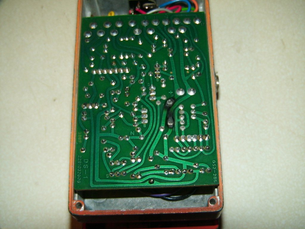
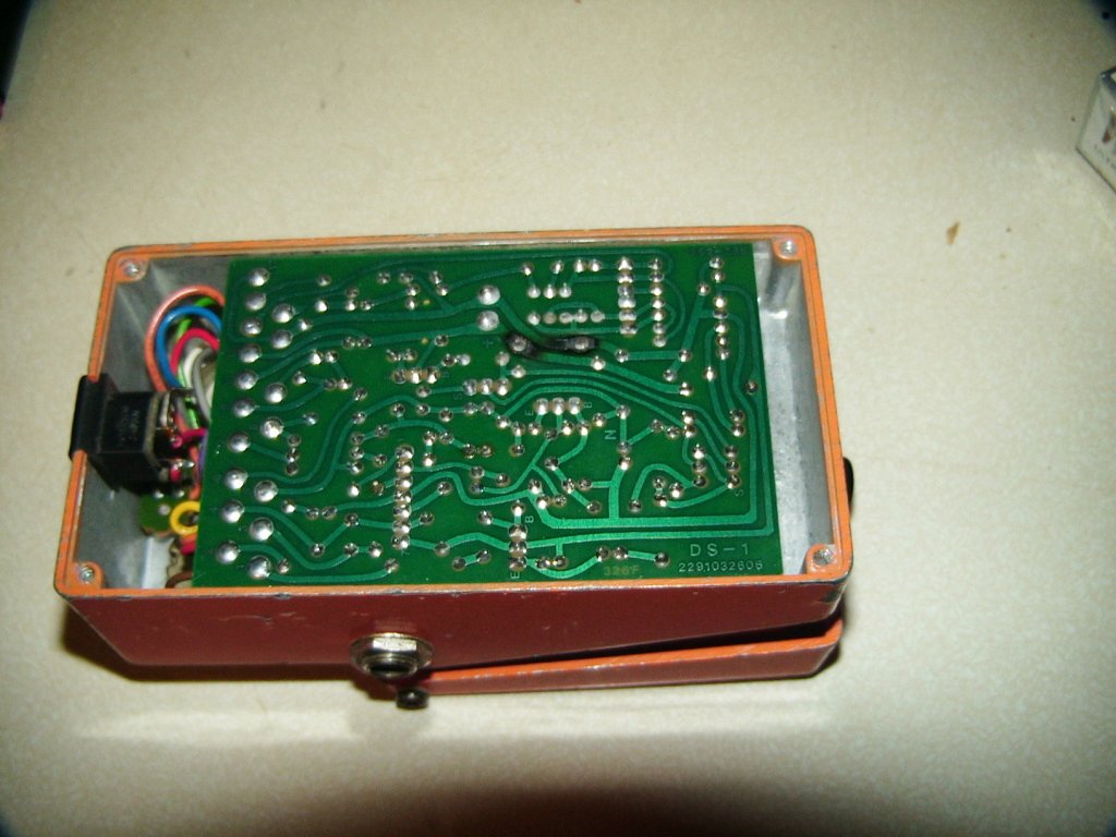
i decided to crack it open to see if anything was wrong... and here's what i found.
i need some help...
1. does the PCB look fried or should that still be okay?
2. what diode exactly is that and what would be a suitable replacement?
thanks in advance. |
|
|
zentropa
Gold Member
USA
837 Posts |
Posted - 03/19/2008 : 07:44:01
|
| ah, well after doing some digging i'm guessing that the diode is a RD11EB3. i'm hoping the board is still okay. |
 |
|
|
ssanyee
Silver Member

Hungary
288 Posts |
Posted - 03/19/2008 : 08:02:10
|
Hello zentropa,
Yes, the PWB can work without major problem with this broken diode as well. I guess somebody have put opposite polarity adaptor and due to this mistake the protector diode has been died! It is sure that the tonal non conformity coming not from this problem.
Do you have schematic?
Are you sure that the problem with the tone knob is a real failure?
cheers |
|
|
|
zentropa
Gold Member
USA
837 Posts |
Posted - 03/19/2008 : 08:41:22
|
thanks for the input. at least i know i wasn't the one that fried it.
i do have a schematic but i'm not educated enough to read it.
the tone problem in question is that when the tone knob is turned past 12 o'clock, the volume starts to decline. at 1 o'clock i lose about 15% volume, at 3 o'clock the volume decrease is about 40% and it stays at that all the way to the right. the tone at 1 o'clock and beyond is VERY thin, tinny, and buzzy (which is a big contrast to the tone at say, 11 o'clock which is incredibly full and warm). i also lose a lot of sustain/signal. i did some tests and a sustained note on the G string of my SG only lasts 7-8 seconds before it dies completely (almost like a noise gate). using my od-3 next to it the same note was sustaining 14-18 seconds and decaying off gradually. i will note that i get similar 14+ second sustain when the tone knob is in the 7 o'clock to 11:30 range. this is my first MIJ DS-1 and the others i have owned were taiwan models that were thin when the tone was up, but not this thin.
this MIJ is by far the best (tone from 7-12 o'clock) and worst (tone from 12-5 o'clock) sounding DS-1 i have ever heard.
does this give any ideas on something else being wrong?
i'm going to pick up a replacement diode tomorrow.
|
Edited by - zentropa on 03/19/2008 08:41:55 |
|
|
|
ChristoMephisto
Platinum Member

Canada
1288 Posts |
Posted - 03/19/2008 : 11:17:52
|
You could also use a 1N4004 diode, or any 1N400x diode.
Easier than looking for a RD11BE3.
Hope there is no hidden damage too.
Alot of people say they like the tone below 12
You tone/volume drop is intersting....
It doesn't look like any comps were changed, am I right?
|
|
|
|
zentropa
Gold Member
USA
837 Posts |
Posted - 03/19/2008 : 11:51:53
|
quote:
It doesn't look like any comps were changed, am I right?
there doesn't appear to be any changes. the person i bought it from was the original owner and basically used it nearly every day for 25+ years.
i'm going to try to hit up a shop tomorrow to see if the newer taiwan ds-1's sound similarly with the tone up.
when my tone knob gets turned up past 2 o'clock i can almost here the wave oscillations trying to cut out... this is with the distortion set to 3 o'clock and the level to like 3-5 o'clock.
it's still the best sounding DS-1 i've ever heard when the tone is below 12 o'clock... that's why it's odd to me.
|
|
|
|
Dr. Bob
Moderator

Australia
6593 Posts |
Posted - 03/19/2008 : 12:24:15

|
quote:
Originally posted by zentropa
ah, well after doing some digging i'm guessing that the diode is a RD11EB3. i'm hoping the board is still okay.
Hi zentropa
From memory, the RD11EB3, is an 11V 1 Watt Zener diode.
It took me a while to figure out why they were using a Zener, & not a
1 Amp, power rectifier diode like the 1N400x (1N4002 - 1N4004).
From what I can figure out, & from experience of changing lots of fried ones.
It appears that, when the Zener fails it typically fails as a short-circuit, the short then protects the rest of the circuit, by not allowing any voltage to get past the short.
Hence the typically charcoaled area on the PCB under the diode,
as it's trying to dissipate, all the reverse voltage energy from the plug pack into heat, which then burns the Bakelite or Fiberglass PCB material.
When a 1N400x fails, (after a very short time), it typically fails as an open-circuit, and allows the full reversed voltage to reach the rest of the circuit.
Which defeats the reason they added the protection circuit-diode in the first place.
Op-amps HATE reverse voltage. (come see my bin of dead ones  ) )
Ask your friend, that used to own the MIJ DS-1, if it was, not just rev. volts, but also possibly slightly over volts.
In your case, the Zener has dissipated enough energy to finally fail as an open-circuit, or worse still may have become resistive, & is loading down the circuit slightly.
It will probably fall in half when you de-solder it.
For testing, it's safe to remove the Zener, as long as you don't apply reverse or over voltage.
I hope this helps.
Regards Dr. Bob
2400
|
Edited by - Dr. Bob on 03/19/2008 12:24:56 |
|
|
|
zentropa
Gold Member
USA
837 Posts |
Posted - 03/19/2008 : 13:30:23
|
unfortunately, i bought the pedal off someone on craigslist and i doubt they would actually admit to doing something that would have fried it.
if they did reverse and over-volt it are there any other components i should be checking? possibly ones that would be giving the tone issue i've tried to describe?
i'm lucky enough to have a place that specializes in these components about 2 miles from where i work and i plan on stopping there on my way to work today. |
|
|
|
Laurie
Double Platinum Member

Canada
4854 Posts |
Posted - 03/19/2008 : 14:44:09
|
G'day! Not related to the tone question... Looking at the pics, I'd think there is a good chance that when you remove the diode that one or both of the burned tracks will go open circuit. If it was mine... I'd probably solder the new zener on the track side of the PCB across the pads of C23 (the big silver discs near the burned bit) then put jumpers over the burned bits. At some point those tracks are gonna fail.
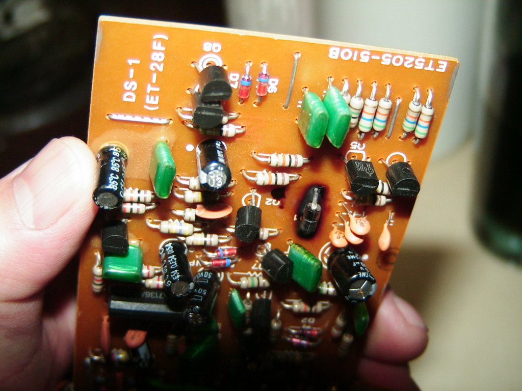
The green capacitor directly "below" the diode in the pic has also taken some serious heat. It's almost certainly problematic too - I'd replace it. It looks like it's the 0.047�F C13 in the schematic I've got (the MIT schematic it slightly different to the MIJ). Anyway, C13 is the main coupling capacitor in the output stage (it drives the main output transistor Q3) and it would definitely affect the tone if it's fried.
C16 looks to have taken heat too, but it's part of the flip-flop and the pedal is still turning on and off OK so it will be OK.
Laurie. |
Edited by - Laurie on 03/19/2008 14:48:02 |
|
|
|
zentropa
Gold Member
USA
837 Posts |
Posted - 03/19/2008 : 17:09:29
|
i will add a .047 cap to my shopping list.
you have me all paranoid now about the pedal failing... would replacing the diode increase its chances of failing since heat will have to be applied to the burn spots? |
|
|
|
Laurie
Double Platinum Member
Canada
4854 Posts |
Posted - 03/19/2008 : 17:44:14
|
quote:
Originally posted by zentropa
would replacing the diode increase its chances of failing since heat will have to be applied to the burn spots?
Yep. The failure would be of the tracks - not the new diode.
But it's easy to fix. See my comments about bridging the tracks above. Those of us who are electronics hackers do it all the time - don't sweat it!
Once we get the diode and burn stuff out of the way, we can look at the tone issue (one thing at a time!) On the bright side, the tone problem might be fixed along the way...
laurie |
Edited by - Laurie on 03/19/2008 17:46:06 |
|
|
|
zentropa
Gold Member
USA
837 Posts |
Posted - 03/19/2008 : 18:05:06
|
i was an engineering major for 2 semesters back in 97-98. unfortunately i rarely went to class during that era of college (even though i got A's... my retention of that material isn't quite what it could have been).
quote:
But it's easy to fix. See my comments about bridging the tracks above. Those of us who are electronics hackers do it all the time - don't sweat it!
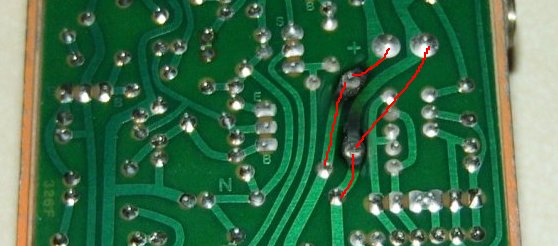
to put this into terms that i understand... basically bridging the tracks = reconnecting the diode before the burned section of track and using wires to bypass the burned parts on the conductive tracks?
would it be something like this?
diode = purple
jumpers = red
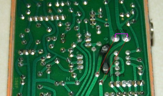
|
|
|
|
zentropa
Gold Member
USA
837 Posts |
Posted - 03/19/2008 : 18:11:37
|
a follow up...
do you recommend trying to put the diode back where it was or just assuming that section is fried?
this will be my first attempt working on a pedal and i really don't want to f it up too badly. and yah, i've been up all night obsessing about this :P |
Edited by - zentropa on 03/19/2008 18:27:58 |
|
|
|
zentropa
Gold Member
USA
837 Posts |
Posted - 03/19/2008 : 18:45:27
|
would popping the diode back in its original spot and then running 2 sets of jumpers work as well? (as pictured below)
thanks again for your patience with me :)
 |
|
|
|
Laurie
Double Platinum Member
Canada
4854 Posts |
Posted - 03/19/2008 : 18:50:47
|
quote:
Originally posted by zentropa
would popping the diode back in its original spot and then running 2 sets of jumpers work as well? (as pictured below)
thanks again for your patience with me :)
Yes, that would work just fine too! And you're welcome mate! |
|
|
|
Laurie
Double Platinum Member
Canada
4854 Posts |
Posted - 03/19/2008 : 18:51:52
|
quote:
Originally posted by zentropa
to put this into terms that i understand... basically bridging the tracks = reconnecting the diode before the burned section of track and using wires to bypass the burned parts on the conductive tracks?
would it be something like this?
diode = purple
jumpers = red
Yes - exactly that. This works too!!
Either one of these approaches works (see my response just above), and neither will have adverse effect on the electrical properties of the circuit.
Again - don't sweat it. The end product won't look pretty, but that's always the case when you are fixing fried boards. this one is an easy fix! I have a an old crown amp that has a big patch of surface-mount components fried on it and a really charred board. The repair looks like a frankenstien's monster, but it's been woking without fault for over two years since I did it.
Laurie |
Edited by - Laurie on 03/19/2008 18:56:53 |
|
|
|
Topic |
|