| Author |
 Topic Topic  |
|
kittenface
Bronze Member

USA
90 Posts |
 Posted - 07/02/2008 : 14:36:05 Posted - 07/02/2008 : 14:36:05


|
I have a DM-2 that needs repairs - any recommendations as to a repair person or shop?
I'm located in Pennsylvania
thanks
Bruce |
Edited by - Dr. Bob on 07/03/2008 16:39:11 |
|
|
Dr. Bob
Moderator

Australia
6593 Posts |
Posted - 07/02/2008 : 15:15:45
|
Hi kittenface
Tell/explain to us, what happened to the pedal before it became faulty.
Like, did it have reverse, or over voltage applied to it?
The Doberman, adopted it as his new CHEW TOY?
Aliens took it away late one evening?
Wife/mum used it as a meat cleaver? - that sort of thing 
You might be able to do a deal with Laurie, to have a look at it for you, he is in Calgary.
Laurie worked out, the definitive recalibration procedure for DM-2's.
Not to mention Laurie is a very trustworthy guy.
The service shops will charge you an arm & a leg for most, even simple repairs.
We have Schematics, if you need them, or can solder, or have a tech friend with a soldering iron.
The old pedals are pretty robust.
We might even be able to help you fix it remotely, via the forum, we have done it for many other pedals & Members.
You might have to upload a few pics, to help us see what the problem might be.
Regards Dr. Bob |
 |
|
|
Laurie
Double Platinum Member

Canada
4854 Posts |
Posted - 07/02/2008 : 16:19:23
|
Yep - I've been knee deep in the guts of my DM-2 recently (how's that for a visual?) - let us know what's happening and we can probably help.
PS: thanks for the kind words Dr. Bob! |
Edited by - Laurie on 07/02/2008 16:20:31 |
|
|
|
kittenface
Bronze Member
USA
90 Posts |
Posted - 07/03/2008 : 12:31:13
|
thanks Doc and Laurie!
I got the pedal from an online auction store - I received it with one of it's chips rattling around loose inside - also there is no battery lead - I will take some good pix later today and post them
thanks again
Bruce |
|
|
|
kittenface
Bronze Member
USA
90 Posts |
Posted - 07/03/2008 : 14:03:39
|
 |
|
|
|
Dr. Bob
Moderator
Australia
6593 Posts |
Posted - 07/03/2008 : 15:10:30
|
Hi kittenface
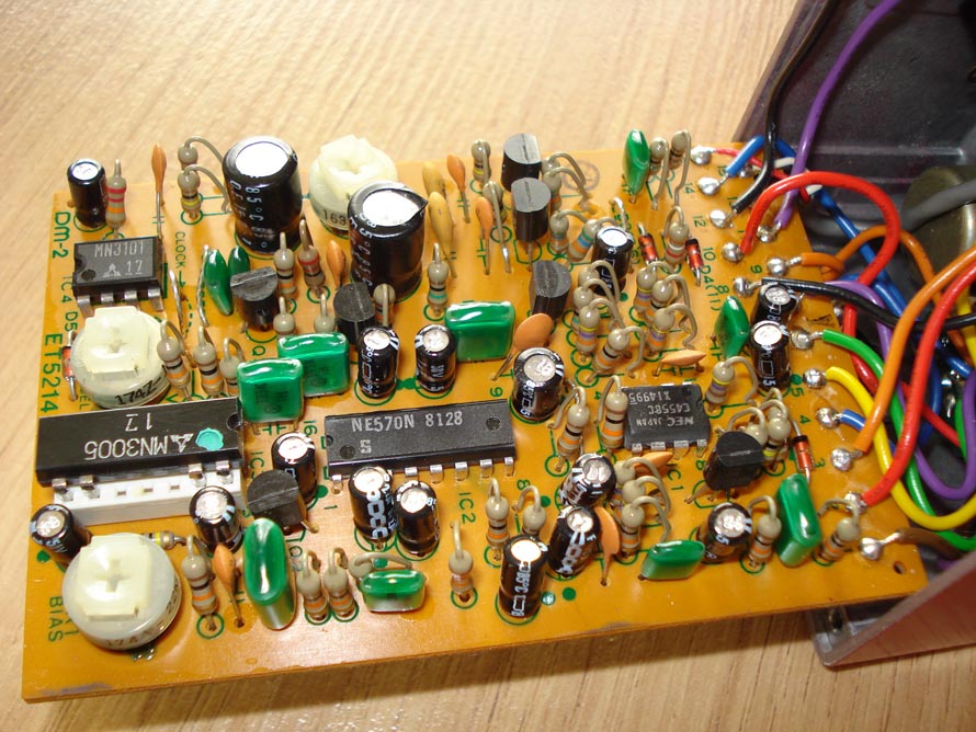
It seems that the BBD delay chip has come out of it's socket.
If you go to this link, near the bottom:
http://www.bossarea.com/forum/topic.asp?TOPIC_ID=4147&whichpage=4
Ssanyee has posted internal pics of his DM-2
Carefully.... Put the IC back into the white IC socket
The IC should still have just 8 legs four at each end.
If you look near the green paint dot, you will see a small notch in the IC's front edge.
Make sure the IC is in the same orientation as the one in Ssanyee's picture.
It will probably then work, even without a battery snap,
on the battery wires, Just insulate any stray threads of wire, with some insulation tape.
All should then be Ok to test with a proper power adapter.
If you are unsure, send some other pics, after you have replaced the IC.
Send a pic of the battery snap wires as well.
You should then have a happy & working DM-2
Here is the Internal picture of Ssanyee's DM-2 from the above link
to make it easier for you, & keeps it on the same page & thread.
Thank you Ssanyee.
See how invaluable a resource, the internal pics thread has now become.
Good Luck kittenface
Remember -- "DON'T Touch the position of the trim pots"
Regards Dr. Bob
|
Edited by - Dr. Bob on 07/03/2008 16:32:59 |
|
|
|
kittenface
Bronze Member
USA
90 Posts |
Posted - 07/04/2008 : 00:23:33
|
I'm off to the beach for the weekend - I'll go at it when I return on Sunday
thanks for the help |
|
|
|
kittenface
Bronze Member
USA
90 Posts |
Posted - 07/07/2008 : 00:27:02
|
ok, moving right along - chip is back in its' socket and the unit works
there is no sign of the battery leads - have a pic where they are supposed to start?
|
|
|
|
Laurie
Double Platinum Member
Canada
4854 Posts |
Posted - 07/07/2008 : 01:27:42
|
Positive lead of battery snap goes to "switched" terminal on the DC-in jack (are there 3 terminals on the DC-in jack, and one of them doesn't have a wire connected?).
Negative lead of battery snap goes to "pin 3" on the board, or more correctly to the pin on the signal input jack that connects to "pin 3".
All of this of course presumes there haven't been any modifications to the pedal wiring... can u post pics of the areas above?
|
|
|
|
Dr. Bob
Moderator
Australia
6593 Posts |
Posted - 07/07/2008 : 08:56:35
|
quote:
Originally posted by kittenface
ok, moving right along - chip is back in its' socket and the unit works
there is no sign of the battery leads - have a pic where they are supposed to start?
Hi kittenface
That's really good news.
Now you'll just have to buy a 9V battery clip & reconnect it.
Are you going to use it on batteries, or a power adapter?
Regards Dr. Bob |
|
|
|
kittenface
Bronze Member
USA
90 Posts |
Posted - 07/10/2008 : 22:36:16
|
if it replaces the DM-3 currently on my board, it will run off a power source - if it doesn't, it'll need to accept a battery
here are pix of the DC input and the input jack - all 3 wires on the DC in jack have wires on them

 |
|
|
|
Laurie
Double Platinum Member
Canada
4854 Posts |
Posted - 07/11/2008 : 16:28:18
|
| Hi kittenface! I'll take a look at your pics on the weekend... |
|
|
|
kittenface
Bronze Member
USA
90 Posts |
Posted - 07/11/2008 : 18:51:07
|
| Thank you very much |
|
|
|
Laurie
Double Platinum Member
Canada
4854 Posts |
Posted - 07/12/2008 : 02:01:23
|
OK... just took the back off my DM-2 and had a look.
The red wire in the middle of the power connector that we can see should go directly to the positive terminal on the battery snap. Where does it actually go?
The black (negative) lead of the battery snap connects to the terminal on the input jack that has the "orange" wire (so it is orange_wire + black_wire_from_battery_snap both soldered to the same lug). It's hard to make out the colour in the pic - on my DM-2 the ornage wire is actually a yellow wire.
|
|
|
|
kittenface
Bronze Member
USA
90 Posts |
Posted - 07/12/2008 : 13:11:54
|
the red wire in the middle of the power connector goes to the output jack terminal closest to the case (the negative or sleeve)
the orange wire on the input jack is the only wire on that terminal
|
|
|
|
Laurie
Double Platinum Member
Canada
4854 Posts |
Posted - 07/12/2008 : 13:50:00
|
OK. There shouldn't be any connection to the output jack sleeve (no need - it gets it's connection from the case itself).
One last question - where does the orange wire go to? It should be terminal 3 on the board? (if not, let us know)
So if the orange wire goes to terminal 3, just buy a battery snap and put the red wire of the snap to the middle of the power connector (remove the wire going from that terminal to the output jack). The black (negative) lead of the battery snap connects to the terminal on the input jack that has the "orange" wire (so it is orange_wire + black_wire_from_battery_snap both soldered to the same lug).
It should be back to standard once you have done that.
Before powering up the pedal, I'd suggest testing with an ohm-meter - plug a lead into the input jack and check between the negative terminal on the snap and terminal 8 on the board - it should be zero ohms (short). And between the positive terminal of the battery snap and terminal 10 on the board - it should be zero ohms (short).
Good luck! |
|
|
|
Topic |
|