| Author |
 Topic Topic  |
|
zentropa
Gold Member

USA
837 Posts |
 Posted - 03/19/2008 : 19:18:28 Posted - 03/19/2008 : 19:18:28


|
Laurie,
thanks a bunch. i feel 100x more confident now.
heading off to the electronics store to buy components.
if you want to take a peak at my OD-1 bleed mod problem feel free :)
|
 |
|
|
zentropa
Gold Member
USA
837 Posts |
Posted - 03/20/2008 : 01:36:38
|
Laurie,
will a polyester-film capacitor work as the .047 uF?
the electronics shop i stopped by earlier today that had metal film ones... i realize just accidentally gave me 0.47 instead of 0.047 so all i have are the polyester ones until tomorrow. |
|
|
|
zentropa
Gold Member
USA
837 Posts |
Posted - 03/20/2008 : 01:38:30
|
| also... the shop's internet was down when i was there (and i forgot to bring a spec sheet) for the RD11EB3 diode... but i remembered Bob's post about it being 11v 1 watt. the closest they had was 12v 1 watt... will that work in its place? |
|
|
|
Laurie
Double Platinum Member

Canada
4854 Posts |
Posted - 03/20/2008 : 02:00:04

|
quote:
Originally posted by zentropa
would popping the diode back in its original spot and then running 2 sets of jumpers work as well? (as pictured below)
thanks again for your patience with me :)
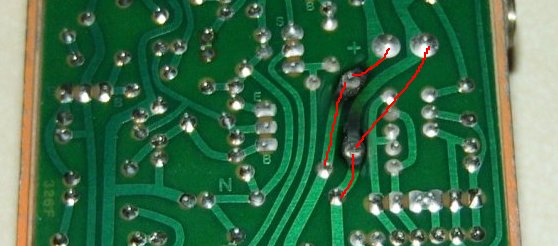
Just had a thought - if you are going to use this method, don't cut the leads of the diode - just lay them down along the tracks and use them as one half of the bridging.
So... at the risk of telling you stuff in terms that are insultingly simple (my apologies if that's the case!), this is how this repair would be approached.
1) desolder the old diode and remove carefully
2) with an exacto knife (or similar) carefully scrape the scorch marks off the tracks. Scrape the varnish off along the red lines in the picture above from the diode heading "down". Be careful to not gouge the copper track, but also be careful to take all the varnish off (it's a fine line but have patience). If some of the copper comes completely away right near the scorch marks, that's normal and OK - just cut it off cleanly.
3) examine the scorched area and see if it is completely burned through - scrape all the burned circuit board away. If it is completely burned through, not to worry - just drill two new holes along the tracks a bit the correct distance apart to take the diode. make sure you miss all the components on the component side of the board if you have to drill new holes...
4) double check all the varnish is removed from the tracks
5) "tin" the cleaned tracks - make sure the soldering iron tip is clean (wipe it on a wet sponge or rag), and apply solder and soldering iron to the tracks until the solder flows along the tracks - don't overheat!
6) put the diode through it�s holes. If the old diode is so fried you can�t see which way around it went, the end with the stripe goes on the same track as the �+� sign near the burns.
7) lay the diode leads along the tinned tracks and solder them down. Don�t overheat! But do use enough heat to get the solder to flow and look nice and silver when it cools.
6) take some insulated light gauge wire and solder jumpers from the diode leads over to the pads on C23. Cut the wire to length, strip and tin it before applying it to the circuit board. Lay it down flat - not "sticking up".
7) use some desolder braid to remove C13. if you don�t have solder braid, it�s messy and not recommended, but you can heat up one of the pads on C13 while pulling the capacitor in the other direction and that will pull that leg out � repeat for the other leg. Don�t overheat!
8) insert new C13 (doesn�t matter which way around it goes) and solder. Don�t overheat! But do use enough heat to get the solder to flow and look nice and silver when it cools.
OK� that should be it. Post a pic of the finished repair? How does it sound now?
Laurie
|
|
|
|
Laurie
Double Platinum Member
Canada
4854 Posts |
Posted - 03/20/2008 : 02:01:06
|
quote:
Originally posted by zentropa
also... the shop's internet was down when i was there (and i forgot to bring a spec sheet) for the RD11EB3 diode... but i remembered Bob's post about it being 11v 1 watt. the closest they had was 12v 1 watt... will that work in its place?
Yes - 12V should be fine. |
|
|
|
Laurie
Double Platinum Member
Canada
4854 Posts |
Posted - 03/20/2008 : 02:02:52
|
quote:
Originally posted by zentropa
Laurie,
will a polyester-film capacitor work as the .047 uF?
the electronics shop i stopped by earlier today that had metal film ones... i realize just accidentally gave me 0.47 instead of 0.047 so all i have are the polyester ones until tomorrow.
I'd use a polyester one without hesitation if it was my pedal, but there are different schools of thought. Worse case - use the polyester one and change it tomorrow if you feel like it?
Actually... looking at the circuit again, the 0.47 one would probably work fine too. Unless I've misread it (Dr. Bob, help me out if I'm telling fibs) it looks to be a coupling cap, so anything around the value will work. FYI - the Keeley mod for this pedal changes it to a 0.1�F
If you are feeling a bit adventurous after getting through all this (later!), the Keeley mods are published here:
http://www.robertkeeley.com/audio6l6/dstech.html
|
Edited by - Laurie on 03/20/2008 02:08:28 |
|
|
|
zentropa
Gold Member
USA
837 Posts |
Posted - 03/20/2008 : 05:18:10
|
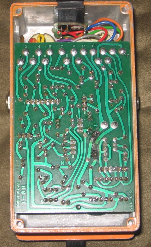
just finished up... and it works.
the good... it works... the tone suck problem is fixed (no longer huge volume decrease nor premature note decay). now it's just a tone suck of a different nature (sounds p00ptastic beyond about 1 o'clock but in a fully functioning way).
the bad... the solder was so baked on it was hard to desolder and remove the old solder. the leads on the new diode were a little larger and when i tried to fit the leads back through the same holes... the track started to tear and pull up from the board. i did my best to press it back down and used a lil extra solder to try and hold it together. i also managed to put a little scratch in the back of the board when i was taking out the cap.
i did not put the jumper wires in... which i realize may turn out to be a mistake but the jumper wire gauge i got is too thick and it won't fit through the hole with the component leads :(
does anyone have a recommendation on a gauge?
i've attached a pic of the finished product (looks very similar to the previous picture but with the track being more crapped up and my clumsy scratch mark).
|
Edited by - zentropa on 03/20/2008 05:19:20 |
|
|
|
zentropa
Gold Member
USA
837 Posts |
Posted - 03/20/2008 : 05:20:42
|
Also a HUGE thank you to everyone who chimed in with help, advice, and tips.
i couldn't have done it without you. |
|
|
|
RonNovy
Copper Member
USA
24 Posts |
Posted - 03/21/2008 : 04:29:56
|
| Arg... Now my DS-1 AND MT-2 is doing this!!! It's gotta be that 12v supply... Time to order some parts! |
|
|
|
Topic |
|