| Author |
 Topic Topic  |
|
paisleyfender
Bronze Member

Germany
70 Posts |
 Posted - 06/06/2006 : 23:06:11 Posted - 06/06/2006 : 23:06:11


|
Thanks so much for your help!
So I think I got the white lead right again.
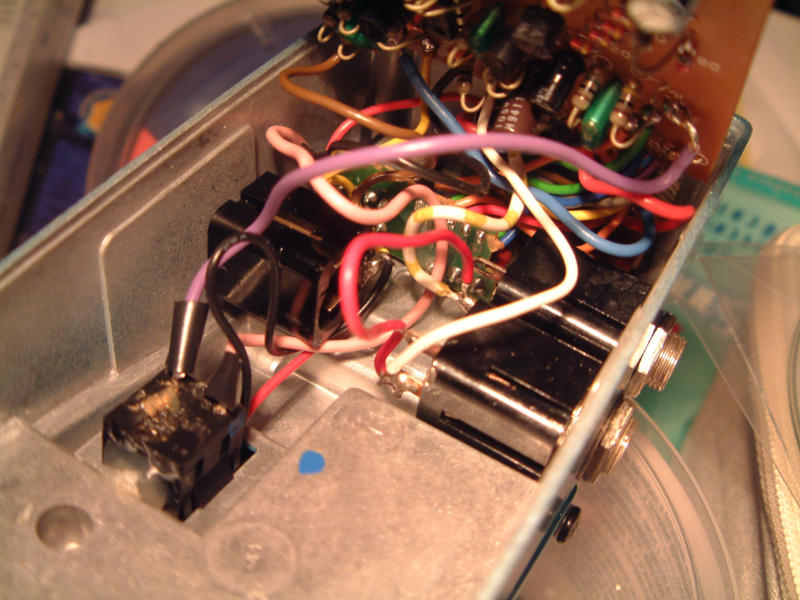
But one detail got my attention: in my CE-3 there is a red wire from one hot output lug to the other, and I don't see that on your picture?
|
 |
|
|
paisleyfender
Bronze Member
Germany
70 Posts |
Posted - 06/06/2006 : 23:08:53
|
Here are the pictures from my CE-3:
Download Attachment:  redlead1.JPG redlead1.JPG
93.36 KB
Download Attachment: redlead2.JPG
78.67 KB |
|
|
|
stahlhart
Platinum Member

1318 Posts |
Posted - 06/06/2006 : 23:13:35
|
Umm -- what's that doing there? Was it Boss who decided to wire the two output signal leads together?
Wouldn't that cancel out the chorus effect in stereo mode?
You sure no one's been in there before you doing mods...? I'd evaluate the pedal's operation both with and without that wire in place (as Bossarea's is probably stock and unmodified).
C.K.
|
|
|
|
bossarea
Forum Admin

United Kingdom
3652 Posts |
Posted - 06/06/2006 : 23:26:01

|
I guess someone has modified yours a bit. Boss normally doesn't put any tape around the solder points on the switch either.
If someone has soldered anything on the PCB you should be able to see it. |
|
|
|
paisleyfender
Bronze Member
Germany
70 Posts |
Posted - 06/07/2006 : 00:55:03
|
The wire cross the outputs doesn't cancel the effect, no.
And without the wire there is no sound at all from output A.
With some solder joints on the pcb I'm not quite sure if they are original. Especially the connection wires seem to be attached rather unprofessional.
But now I'm rather demotivated to put more energy in finding the error in this little bastard, so I will eventually leave this to someone with more experience in repairing electronic equipment.
And bossarea, for me you don't have to back engineer the schematic, that seems to be much to much effort for me.
But thanks again to all of you, this forum is just a great place for all BOSS pedal enthusiasts! |
|
|
|
stahlhart
Platinum Member
1318 Posts |
Posted - 06/07/2006 : 01:17:19
|
In Mode I, the signal at the A output jack is a combination of the direct signal plus a positive-phase effect signal (direct+effect), while the signal at the B output jack is a combination of the direct signal plus a reverse-polarity effect signal (direct-effect). The two outputs can be further combined and sent separately to two amps in order to create a true, wide stage stereo chorus sound with a lush, swirling and deep effect.
In Mode II, only the effect signalis sent to the output jack, and the B output jack receives no effect signal at all. This is the same configuration found on the original CE-1 and on Roland's well-known Jazz Chorus Amplifiers.
When Using the monaural setting, set the Stereo Mode control to Mode I.
So that red wire was someone putting a band-aid over a more serious problem, it seems. In Mode I you should have effected output on both A and B, and it would seem to me that tying them together would cancel out the effect, since they're out of phase (Bossarea, do you have a Y cable that could be used to verify this?). If you're not getting any audio out of one of the outputs in Mode I, then the red wire is simply putting one side out of both jacks.
C.K.
|
|
|
|
bossarea
Forum Admin
United Kingdom
3652 Posts |
Posted - 06/07/2006 : 14:56:45
|
When I opened it up and saw how close the components were I quickly dismissed the idea about drawing up the schematic. It would be much less work to make a call to Roland and order a copy  |
|
|
|
stahlhart
Platinum Member
1318 Posts |
Posted - 06/07/2006 : 18:10:07
|
quote:
Originally posted by bossarea
When I opened it up and saw how close the components were I quickly dismissed the idea about drawing up the schematic. It would be much less work to make a call to Roland and order a copy
It's not a fun job at all. And my eyesight is no longer what it was in my 20s, which would just add to that. But back then I had no choice -- the flanger was broken, and I was troubleshooting blindly without it.
But I got it working, and learned a lot about how an analog delay circuit works in the process, so it was worth it in the long run.
I've since found a few revisions of hand-drawn Electric Mistress schematics online in the past year or so, so thankfully there are others pursuing the service documentation on these pedals now.
The other part of the story I forgot to add was how I ended up damaging the traces on the original circuit board as a consequence of repeated soldering/desoldering, and had to had draw and etch a new board for that pedal. And then the unfortunate accident I had when I stupidly decided to use an old aluminum pie tin for the etching process.    I sold that pedal many years ago, but I still have the original circuit board in my parts bin (I kept it for schematic cross-reference). I sold that pedal many years ago, but I still have the original circuit board in my parts bin (I kept it for schematic cross-reference).
C.K.
|
|
|
|
Topic |
|
 redlead1.JPG
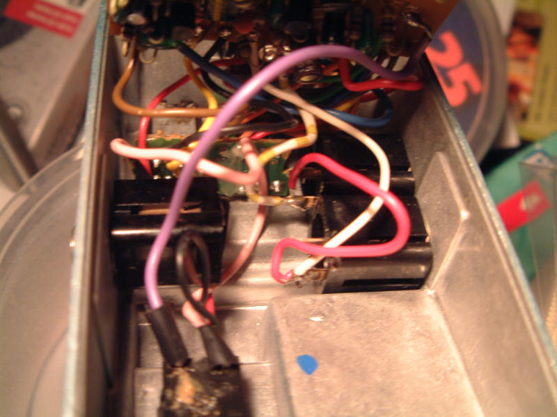 redlead2.JPG