| Author |
 Topic Topic  |
|
ChristoMephisto
Platinum Member

Canada
1288 Posts |
 Posted - 03/14/2008 : 11:24:42 Posted - 03/14/2008 : 11:24:42


|
Looking at the schem for the mod on the SD1, it would be the same for both 14 pin and 8 pin versions of the OD1.
good luck |
 |
|
|
zentropa
Gold Member

USA
837 Posts |
Posted - 03/15/2008 : 02:46:10

|
thanks.
i will look to tracking down the parts for it in the very near future. |
|
|
|
zentropa
Gold Member
USA
837 Posts |
Posted - 03/19/2008 : 07:13:22
|
Christo or anyone,
unfortunately, I haven't done any schematic reading since ~1997 (when i was a physics/engineering major in college) and i haven't been able to track down an actual schematic for the SD-1 bleed fix.
the only bleed fix info i've seen was this:
http://www.indyguitarist.com/temp/sd1-bypass-fix-406.gif
do you know how that would correspond to the OD-1 8-pin?
i hate feeling helpless... i swear i'm going to dig out my old textbooks and learn how to read this stuff again.
 |
|
|
|
ChristoMephisto
Platinum Member
Canada
1288 Posts |
Posted - 03/19/2008 : 11:25:52
|
Same areas, different reference designators.
SD-1 to OD-1 8 pin,
D8 is D9 neg side
R6 is the same, top
R7 is also the same, bottom
good kuck |
|
|
|
zentropa
Gold Member
USA
837 Posts |
Posted - 03/19/2008 : 12:16:10
|
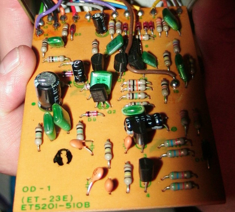
my apologies for the continued questions, but doing any of these mods myself on my OD-1 terrifies me and i hate the thought of jumping into something without knowing exactly how it's supposed to be...
are these the right ones?
i've been meaning to find some cheaper taiwan pedals to practice on, but they aren't in my budget right now.

also wondering... aside from accidentally frying something during soldering, none of these could actually hurt the pedal if i accidentally connected to the wrong one would it? |
Edited by - zentropa on 03/19/2008 12:17:22 |
|
|
|
Dr. Bob
Moderator

Australia
6593 Posts |
Posted - 03/19/2008 : 12:53:57

|
Hi zentropa
Just a quick note:
It looks like your edited pic, didn't upload correctly.
You will probably have to rename it & try again, I think that forum's server won't let you over-right the old file.
Then just edit your post, to reflect the new file name,
make it something similar, like myFile to myFile2.
Regards Dr. Bob |
Edited by - Dr. Bob on 03/19/2008 12:58:47 |
|
|
|
Dr. Bob
Moderator
Australia
6593 Posts |
Posted - 03/19/2008 : 13:00:20
|
Hey zentropa
Can I ask you what all the numbers on the IC are?
And is it a Rev. E OD-1?
It's printed on the copper-foil side of the PCB, opposite end to the wires.
RHS Bottom, looking at the pedal with the knobs up, battery screw nearest you.
Regards Dr. Bob |
|
|
|
zentropa
Gold Member
USA
837 Posts |
Posted - 03/19/2008 : 13:27:54
|
Bob:
it's a revision E: 052-281E
other numbers: 2291032105
IC is a JRC4558DD
as for the pic, it crashed during uploading but it did get the 2 resistors i circled which are the ones i'm uncertain about.
at the shop i shot this one out for 90 mins against a revision D. The D had a bigger volume boost, but this one was sooooooooo much smoother and warmer on the gain. |
|
|
|
ChristoMephisto
Platinum Member
Canada
1288 Posts |
Posted - 03/19/2008 : 23:02:31
|
your board doesn't have the designators printed on them.
R7 is the 4k7 (red-purp-orange)resistor above the opamp
which side the green mod wire would go depends on which end goes to the opamp. In the mod, it is between the opamp pin7 and R7, its the same for the OD1. Look on the back and follow the tracks, and figure which end of the resistor leads to pin7. I'm using the service notes from both the SD1 and OD1. I don't have a OD1 to tell you the proper end.
|
Edited by - ChristoMephisto on 03/19/2008 23:03:55 |
|
|
|
zentropa
Gold Member
USA
837 Posts |
Posted - 03/20/2008 : 01:35:29
|
Thanks Christo.
if i stare at the diff schematics long enough will i find out which R6 is supposed to be? |
|
|
|
Laurie
Double Platinum Member

Canada
4854 Posts |
Posted - 03/20/2008 : 02:58:21
|
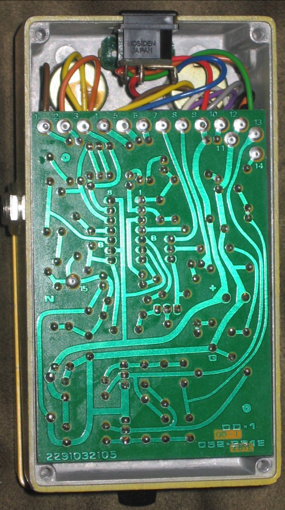
zentropa - post a clear pic of the track side of the board (same way up as the conponent side pic you posted - just turn it over) and we'll be able to help you out.
Laurie |
|
|
|
zentropa
Gold Member
USA
837 Posts |
Posted - 03/20/2008 : 04:03:38
|
here is a pic of the back.
actually doing the bleed fix on my friend's sd-1 tomorrow assuming i don't ruin my DS-1 tonight :) figured worst case i can probably study his board layout and hopefully figure it out.
 |
|
|
|
Laurie
Double Platinum Member
Canada
4854 Posts |
Posted - 03/20/2008 : 04:18:46
|
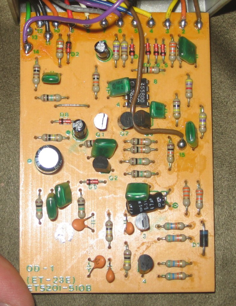
Great pic! One last request... a pic of the component side of the board from vertically above (rather than angled like the one previously).
I'll find some time probably tomorrow to work it out. |
|
|
|
zentropa
Gold Member
USA
837 Posts |
Posted - 03/20/2008 : 04:24:58
|
thanks again.
here's the front pic.
 |
|
|
|
ChristoMephisto
Platinum Member
Canada
1288 Posts |
Posted - 03/20/2008 : 10:40:58
|
All right, good stuff. Its the right hand side of the R7 resistor.
noticed i told you the wrong value too, its the 10k resistor we're looking for, i got it mixed with the R6 value
This site has the service notes for your OD1, it also shows the pcb layout, and what comps are where
http://www.godiksennet.com/default.asp?main=Schematics |
|
|
|
Topic |
|