| Author |
 Topic Topic  |
|
|
ashtone
Copper Member
15 Posts |
 Posted - 02/02/2007 : 19:51:30 Posted - 02/02/2007 : 19:51:30


|
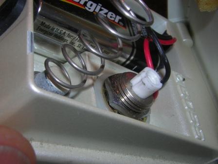
I have developed a mod that puts a true bypass A/B switcher inside your Boss pedal. It utilizes a 4PDT mechanical switch, which replaces the factory on/off switch with no mods to the pedal (no holes to drill for this switch). A two-color LED that shows the status of the A/B loop (red = on, green = bypass)goes where the original LED is located. You can maintain stereo output (where applicable), and you can still use a battery if you wish. It is a simple design, but it is not a "beginners" project. You have to partially disassemble the pedal, access the circuit board, de-solder and jumper the FET switching parts so the circuit is always on, and put it all back together correctly. Good soldering skills are essential.
In operation, you step on the pedal just like normal, and the LED changes color to show you whether the effect is in or out of your signal path. I don't want to modify pedals, I want to sell a kit with detailed instructions, photos and all parts necessary. What I'm requesting from people at this point is if the price is reasonable, and whether there is enough interest. I'm thinking it will be about $50.00. All components are of the highest quality available, and they are all engineered to fit comfortably in the case and function properly for the life of the pedal. It has been thoroughly field tested by guitarists in live stage situations for more than two years and there have been NO failures.
So, what would you get for your 50 bucks? The kit will include all parts needed, including some solder wick for de-soldering existing connections. I am considering the option of an upgrade kit that would include Switchcraft jacks, but it would require slightly reaming the holes in the case to fit the new jacks, so I'm not sure about that yet. Let me know if you think it's a desireable option. The kit will be partially pre-assembled: the 4PDT switch will be pre-wired using the factory colors. These wires will need to be trimmed to length and soldered to the jacks and circuit board. The LED will be pre-wired with the correct voltage drop resistor and factory colored wires. All solder lugs will be insulated with heat-shrink. It takes me, having done about 17 pedals, about four hours to complete. I would guess that with detailed instructions, photos and the pre-wired parts, it would take the same amount of time for you to do it. Again, this is an advanced project due to the "invasive" nature of the mod, so some skill is required.
Please let me know what you think about this; there is a large DIY community out there, and I hope this is something people will want to do. I will shortly post photos of a couple of my pedals so you can check it out.
Download Attachment:  DD-5 comp.jpg DD-5 comp.jpg
21.75 KB
Download Attachment: DC-2 comp.jpg
16.56 KB |
Edited by - ashtone on 02/10/2007 17:24:44 |
|
|
DeFrag
Moderator

USA
3409 Posts |
Posted - 02/04/2007 : 02:52:29


|
| That's a decent job. |
 |
|
|
ashtone
Copper Member
15 Posts |
Posted - 02/05/2007 : 04:44:49
|
| Thanks. It was a "labor of love", if you know what I mean. |
Edited by - ashtone on 02/05/2007 04:56:32 |
|
|
|
stinkfoot
Silver Member

Sweden
181 Posts |
Posted - 02/07/2007 : 00:38:05
|
Nice job! I've seen people fit DPDT and 3PDT switches in Boss cases before, but it has never really been done on any regular scale. To me, the work involved (trimming the switch actuator down to make the thing fit and switch when you want it to) has always been something of a turn-off. I have a couple of DPDT switches that might fit, but then I'd have to add a Millennium circuit to run the LED.
Anyway, in most Boss/Ibanez-type pedals, it's quite easy to "hot-wire" the flip-flop circuit to stay always on. Usually, it will be as simple as removing a single transistor, and the pedal will stay in "active" mode at all times. Some pedals use more advanced logic circuits in place of the more traditional flip-flops, in which case one could hotwire the circuit by removing the FET carrying the dry signal and jumpering the one carrying the effected signal. That way, you'd be able to skip the extra switch, and use the stock LED for on/off indication.
/Andreas |
|
|
|
ashtone
Copper Member
15 Posts |
Posted - 02/09/2007 : 01:46:50
|
Thanks for your suggestions! That is exactly the kind of thing I'd be interested in learning about. My electronic knowledge is pretty rudimentary; I'm a guitarist who spent many years in search of my idea of tone, and figuring out how to get around the "roadblocks" I came up against. I can figure stuff out if I have enough time and information, and I really enjoy the process. But it's at times like this when I am humbled by my lack of electronic education. So are there schematics for Boss pedals available somewhere? You mentioned jumpering or bypassing transistors to eliminate the FET switching, which I would agree is a better way to do it. How would I learn to identify that component and rewire it in both the digital and analog pedals? I also agree that by hardwiring the FET to be hot, the stock indicator becomes redundant and I can put the dual-color LED in that hole, thus eliminating drilling those two holes. So can you point me in the right direction? I imagine once I can locate these components on my Boss pedals, locating them on the Ibanez circuit board would be easy. Here is a pictures of one of two overdrive circuits I designed. The first prototype was on perf board. I drew out the PC traces, and had about 50 of each one (two types) made up so I could figure out the differences between different types of components. Tantalum or electrolytic, carbon or metal film, that kind of thing. I used a meter to closely match the parts from board to board, and they use 10-pin headers so I can pop them in and out of my pedal easily. I originally used the IC most people seem to like, the 4558. After trying lots of cross-referenced substitutions, I really dig the 5532 variant.
Download Attachment: circuitB.JPG
32�KB |
Edited by - ashtone on 02/09/2007 03:19:46 |
|
|
|
RossL
Bronze Member

USA
63 Posts |
Posted - 02/09/2007 : 15:32:52
|
| What does the small switch on the outside of the box do? |
|
|
|
stinkfoot
Silver Member
Sweden
181 Posts |
Posted - 02/10/2007 : 02:05:35
|
quote:
Originally posted by ashtone
So are there schematics for Boss pedals available somewhere?
Many of them can be found on the net - do a google search (e.g. "boss ds-1 schematic") and something will usually pop up.
quote:
You mentioned jumpering or bypassing transistors to eliminate the FET switching, which I would agree is a better way to do it. How would I learn to identify that component and rewire it in both the digital and analog pedals?
Well, having the schematic for the pedal in question will help a lot. For instance, in the DS-1, Q4 and Q5 control the flip-flop switching. Removing the correct one from that pair will make the pedal stay "on" at all times. Off the top of my head, I can't remember which one of them it is, but try removing one of them and see if the pedal stays "on" or "off". If it stays off, put the transistor back and remove the other one instead.
Take note of how the flip-flop circuit looks in the schematic, as it will look mostly the same in many other pedals. That will help you identify the components in those pedals too.
Remember that you're only altering the circuit that controls the signal-carrying transistors - if you want to hard-wire the signal path instead, you need to identify those transistors, remove them and jumper the right connection to open the circuit's path to the output. This is a bit more complex, and requires a fair bit of schematics reading skills.
Also, the more complicated the circuit, the harder it will be to find the right components. Some of the more advanced pedals don't even have the traditional flip-flop circuit, and those will need other methods (hardwiring the signal path, for instance). But all pedals' circuits can be made to stay "on" - it's just a matter of knowing how to do it.
/Andreas |
|
|
|
DeFrag
Moderator
USA
3409 Posts |
Posted - 02/10/2007 : 03:36:00
|
I couldn't find an LS-2 schem for the life of me!  |
|
|
|
ashtone
Copper Member
15 Posts |
Posted - 02/10/2007 : 09:31:41
|
quote:
Originally posted by RossL
What does the small switch on the outside of the box do?
As mentioned in the original post, it turns the pedal on if it powers up in the "off" mode, but I as Andreas said above, it can be done by hardwiring the circuitry. And if you read further, you'll see that the extra LED can go where the factory one went. |
|
|
|
Indyguitarist
Copper Member
USA
18 Posts |
Posted - 02/13/2007 : 01:51:08
|
http://www.indyguitarist.com/schematics/boss/ for schems.
In particular, the ds-1 schem is here:
http://www.indyguitarist.com/schematics/boss/DS1PG2.jpg
Where did you get the 4pdt switch?
If it was me, I'd remove Q6, Q7, and Q8. Then jumper from c2 - c3 and from r16-c13 (where the holes of the jfet were. Then wire up your bypass switch as normal. However, 4 hours seems quite long!! I would think doing the mod this way may take an hour, maybe 2 unless you have to tear apart the switch and grind down the actuator and that sort of thing.
You won't need to wire a momentary switch this way though.
Andreas, you may/may not remember when CD from Aron's forum did this mod with the stock momentary switch and just wired in a relay in the pedal. That's another option but IIRC not much room for the relays.
Ash, you can see a similar drawing of a TB mod I drew up for someone on Aron's forum if you look here:
http://aronnelson.com/gallery/Brian-Wampler-Indyguitarist/temp_boss_os2_truebypass?full=1
Hope that helps! :)
bw
|
|
|
|
ashtone
Copper Member
15 Posts |
Posted - 02/17/2007 : 20:10:55
|
Where did you get the 4pdt switch?
It came from Mouser, and is about $26. There are two styles; one has a miniature collar with a metal actuator (see DC-2 attachment above), and the other has a full-sized shaft with a plastic actuator(DD-5 attachment above). The plastic one works really well in a TubeScreamer because there is a little pin on the underside of the switch tread you step on which fits into the recess on the actuator. The miniature metal shaft works well in the boss pedals, where the lid comes down to push the actuator.
4 hours seems quite long!! I would think doing the mod this way may take an hour, maybe 2 unless you have to tear apart the switch and grind down the actuator and that sort of thing.
I took the everything out of the case, drilled it for the two extra parts I was using, installed the 4pdt switch , adjusted the switch to find the sweet spot where it latched and unlatched properly (using the lid like normal), re-wired the circuit board connections to the jacks and new switch, tapped the hole for the pin switch so I could screw it in (because I don't like the look of those little hex nuts) and re-assembled everything. A DS-1 would probably be easier than a DD-5, since there is less inside the DS-1. Maybe it was less than four hours, but not much.
Thanks for the tips on the schematics.
|
Edited by - ashtone on 02/17/2007 20:23:28 |
|
|
| |
Topic |
|
|
|
 DD-5 comp.jpg
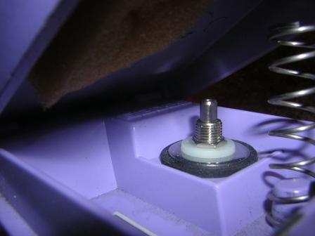 DC-2 comp.jpg
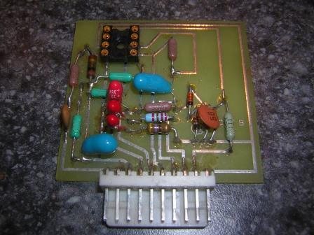 circuitB.JPG