| Author |
 Topic Topic  |
|
|
Ollie
Gold Member

United Kingdom
729 Posts |
|
|
Mesjoggah
Gold Member
Netherlands
595 Posts |
 Posted - 05/11/2009 : 22:46:03 Posted - 05/11/2009 : 22:46:03


|
| Never seen a modded MD-2, could be interesting though! |
 |
|
|
DasBeef
Gold Member
United Kingdom
704 Posts |
Posted - 05/11/2009 : 23:59:50

|
| The SD-2 mod sounds pretty sweet! |
|
|
|
cctsim
Silver Member

United Kingdom
418 Posts |
Posted - 05/12/2009 : 02:45:52
|
Isn't MD-2 a digital pedal ?
I am now curious what could be modified in such a pedal. |
|
|
|
Laurie
Double Platinum Member

Canada
4854 Posts |
Posted - 05/12/2009 : 05:04:18
|
quote:
Originally posted by cctsim
Isn't MD-2 a digital pedal ?
I am now curious what could be modified in such a pedal.
|
|
|
|
cctsim
Silver Member
United Kingdom
418 Posts |
Posted - 05/12/2009 : 23:43:18
|
Definitely analog then.
Any kind soul with a schematic for MD-2 ? |
|
|
|
Laurie
Double Platinum Member
Canada
4854 Posts |
Posted - 05/12/2009 : 23:54:45
|
Me too please for the schem!
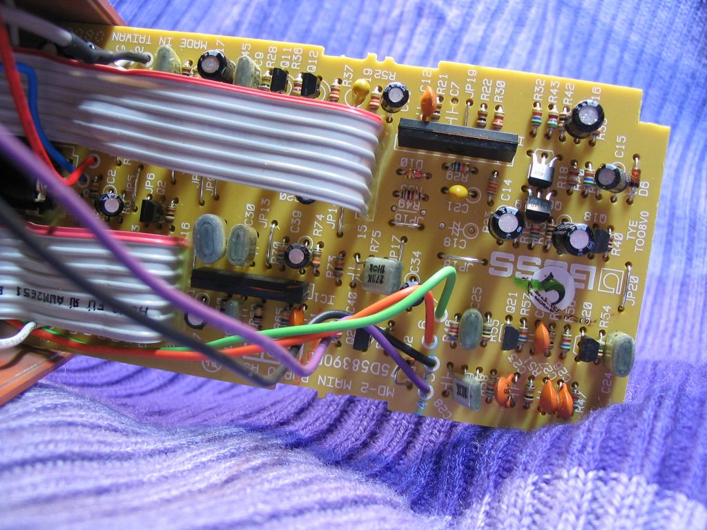
Interesting how C18, R49, C7 were never there - the solder shows that the holes were empty when the board was made.
|
|
|
|
tunghaichuan
Bronze Member

USA
77 Posts |
|
|
ChristoMephisto
Platinum Member

Canada
1288 Posts |
Posted - 05/13/2009 : 00:21:46
|
This should get your solder iron hot...
Max distortion
R37 1K Increases distortion capability along with c19
C19 .47UF
C7 1k
R22 1K
R30 100K Stock is 22k. The larger the value, the more gain.
R23 10K
It should be noted that with any circuit there will be a max
�usable� distortion, and anything past that just adds noise, hum,
and hiss. If you are experiencing this, simply change the values
listed (in relation to the schematic).
Overdrive tones
R37 1K changing the first frequencies clipped here.
R71 1k
R21 470k
C7 470pf
R30 47k
R75 2 � 1n4148 diodes connect in parallel, opposite directions.
R73 Jumper
C40 .008uf Rolls off some of the 'fizz'
More mids
R61 Install 4.7k trim pot
changing the value of r61 will change the frequency that the "bottom� knob controls.
C9 .0047
C7 .0047
R21 47k
|
|
|
|
Laurie
Double Platinum Member
Canada
4854 Posts |
Posted - 05/13/2009 : 00:29:30
|
| Thanks! |
|
|
|
Mesjoggah
Gold Member
Netherlands
595 Posts |
Posted - 05/13/2009 : 05:31:15
|
quote:
Originally posted by ChristoMephisto
This should get your solder iron hot...
Max distortion
R37 1K Increases distortion capability along with c19
C19 .47UF
C7 1k
R22 1K
R30 100K Stock is 22k. The larger the value, the more gain.
R23 10K
It should be noted that with any circuit there will be a max
�usable� distortion, and anything past that just adds noise, hum,
and hiss. If you are experiencing this, simply change the values
listed (in relation to the schematic).
Overdrive tones
R37 1K changing the first frequencies clipped here.
R71 1k
R21 470k
C7 470pf
R30 47k
R75 2 � 1n4148 diodes connect in parallel, opposite directions.
R73 Jumper
C40 .008uf Rolls off some of the 'fizz'
More mids
R61 Install 4.7k trim pot
changing the value of r61 will change the frequency that the "bottom� knob controls.
C9 .0047
C7 .0047
R21 47k
That's Brian Wampler's Indyguitarist mod, he also wrote this:
Jumper Mod
This mod entails removing part of the stock circuit out of the signal path. You will
need to follow along closely with the schematic, as this is a bit of an 'advanced' mod,
though it will make the pedal considerably better sounding.
Find r23 and c14. Where the two of them meet (looking at the circuitboard traces),
you will want to remove c14, and install one end of a wire in the hole that is
connected to r23.
Remove Q23, R72, and find the hole r72 hole that is connected to r69. Insert the
other end of the wire here.
This is removing the gritty and fizzy �mu-amp� circuit and the buffer immediately
after. Basically, you are connecting R23 to R69 while removing the mu-amp and
buffer from the circuitry. |
|
|
|
cctsim
Silver Member
United Kingdom
418 Posts |
Posted - 05/13/2009 : 22:20:58
|
It looks like there is a push-pull amp section in the middle of the circuit (between the 47uF and 1uF electrolytics).
So much for Zvex's claim that they are the first to use such a distortion circuit.
I bet this section adds a lot of harshness in the sound of MD-2 because of the crossover distortion inherent in this structure.
A possibly nice mod would be to take the 1uF electrolytic out and short out this section.
 |
|
|
|
Dr. Bob
Moderator

Australia
6593 Posts |
Posted - 05/14/2009 : 14:50:24
|
Hi cctsim & Guys
As I don't Yet own an MD-2, how do they actually sound.
I have never been a fan of Crossover Distortion.
No Wonder one of the mods is to completely bypass this stage.
I have heard the ZVex pedal & it's definitely a pedal I won't be chasing.
I'm not that experimental.
Regards Dr. Bob 
|
|
|
| |
Topic |
|